English...3 Français...20 中文
|
|
|
- 衩 荀
- 6 years ago
- Views:
Transcription
1 DOC MET ONE /2013, Edition 1, Firmware version 4.08.XX Basic User Manual Manuel d'utilisation de base 基本用户手册
2 English...3 Français...20 中文
3 Table of Contents Specification Detail Specifications on page 3 Operation on page 16 General information on page 4 Maintenance on page 18 Installation on page 8 Particle counter navigation on page 16 Additional information Diagnostics and Troubleshooting on page 19 Additional information is available on the manufacturer's website. Specifications Specifications are subject to change without notice. Instrument specifications Specification Power requirement Installation category Protection class Pollution degree 2 Altitude Light source Pump type Count display Interface Detail VAC, 3.4 A maximum, Hz to the ACto-DC power supply; 24 VDC and 75 W to the instrument I III 2000 m (6562 ft) Helium-neon laser, Class 3R Laser (IEC/EN), Class 3A Laser (CDRH), 5 mw maximum at nm Air vacuum, rated for continuous use Color ¼ VGA TFT touch screen Windows CE -based Maximum count shown 9,999,999 Delay time 00:00:06 to 23:59:59 Sample and hold times 00:00:01 to 23:59:59 Count alarms Data storage Count cycles Locations Up to 999 Exhaust port Outputs Manifold Communication protocols Inputs Auto CDA purge Enclosure material Weight without battery 1 to 9,999,999 counts 50 to 5000 samples, scrollable on Historical Data review screen 3000 is the default value Up to 100 while in automatic mode 3/8-in. NPT thread Ethernet 10Base-T/100Base-TX RS485 Serial RS232 Serial Optional wireless b/g compatible USB Client (Version 1.1) USB Host (Version 1.1) Auxiliary (alarm and scan probe) Supports A3432, 32-port manifold system (available on 1 CFM units only) Modbus TCP, Modbus RTU, Serial FX Air velocity probe, relative humidity/temperature probe Purge solenoid activated by connection to CDA Stainless steel (passivated) 15.9 kg (35 lb) English 3
4 Specification Detail Specification Detail Size (W x D x H) Environment, operation Environment, storage Certifications 33 x 56 x 23 cm (13 x 22 x 9 in.) including protrusions, handles and feet 0 to 40 C (32 to 104 F); 10 to 90% relative humidity, non-condensing 40 to 50 C ( 40 to 122 F); 0 to 98% relative humidity, non-condensing CE, C-Tick, KC, FCC, IC, CDRH laser accession no Sample measurement specifications Sampling Particle size ranges and standard channels Flow rate Zero count Coincidence loss Count efficiency Battery specifications Specification Battery type 0.1, 0.2, 0.3, 0.5, 1.0, 5.0 µm 28.3 L/min (1.00 cfm) ± 5% (default factory setting) Conforms to ISO and JIS B count or less in 5 minutes, 95% confidence level 5% at 1,765,000 particles/m 3 (50,000 particles/ft 3 ) per ISO method 50% for 0.1 μm; 100% for 0.15 μm. Fully complies with ISO and JIS B Detail Battery life during operation 3 hours minimum 1 Battery recharge time Lithium ion smart battery; can be charged, ejected and changed without disruption to the system hours minimum, 10 hours maximum Power Battery weight 14.4 VDC, 6.6 Ah (2x) 0.66 kg (1.45 lb) 1 With two fully-charged batteries in a 1.0 CFM unit sampling for 20 minutes (1 m 3 sample), print record, a 5-minute hold time (simulating a move to new location), then repeating this cycle. The backlight time-out set to 2 minutes. General information In no event will the manufacturer be liable for direct, indirect, special, incidental or consequential damages resulting from any defect or omission in this manual. The manufacturer reserves the right to make changes in this manual and the products it describes at any time, without notice or obligation. Revised editions are found on the manufacturer s website. Safety information N O T I C E The manufacturer is not responsible for any damages due to misapplication or misuse of this product including, without limitation, direct, incidental and consequential damages, and disclaims such damages to the full extent permitted under applicable law. The user is solely responsible to identify critical application risks and install appropriate mechanisms to protect processes during a possible equipment malfunction. Please read this entire manual before unpacking, setting up or operating this equipment. Pay attention to all danger and caution statements. Failure to do so could result in serious injury to the operator or damage to the equipment. Make sure that the protection provided by this equipment is not impaired. Do not use or install this equipment in any manner other than that specified in this manual. Use of hazard information D A N G E R Indicates a potentially or imminently hazardous situation which, if not avoided, will result in death or serious injury. 4 English
5 W A R N I N G Indicates a potentially or imminently hazardous situation which, if not avoided, could result in death or serious injury. C A U T I O N Indicates a potentially hazardous situation that may result in minor or moderate injury. N O T I C E Indicates a situation which, if not avoided, may cause damage to the instrument. Information that requires special emphasis. Precautionary labels Read all labels and tags attached to the instrument. Personal injury or damage to the instrument could occur if not observed. A symbol on the instrument is referenced in the manual with a precautionary statement. This symbol, if noted on the instrument, references the instruction manual for operation and/or safety information. This symbol, when noted on a product enclosure or barrier, indicates that a risk of electrical shock and/or electrocution exists. Delicate internal electronic components can be damaged by static electricity, resulting in degraded performance or eventual failure. This symbol indicates a laser device is used in the equipment. Compliance This symbol identifies the location of a fuse or current limiting device. Electrical equipment marked with this symbol may not be disposed of in European public disposal systems after 12 August of In conformity with European local and national regulations (EU Directive 2002/96/EC), European electrical equipment users must now return old or end-of-life equipment to the Producer for disposal at no charge to the user. Note: For return for recycling, please contact the equipment producer or supplier for instructions on how to return end-of-life equipment, producer-supplied electrical accessories, and all auxillary items for proper disposal. This symbol indicates that the instrument is a Class 1 LASER product. This product complies with IEC/EN :2007 and 21 CFR except for deviations pursuant to Laser Notice No. 50, dated June 24, FDA accession number: This product is also CE compliant. Contact the manufacturer for complete compliance details. Certification Canadian Radio Interference-Causing Equipment Regulation, IECS-003, Class A: Supporting test records reside with the manufacturer. This Class A digital apparatus meets all requirements of the Canadian Interference-Causing Equipment Regulations. Cet appareil numérique de classe A répond à toutes les exigences de la réglementation canadienne sur les équipements provoquant des interférences. FCC Part 15, Class "A" Limits English 5
6 Supporting test records reside with the manufacturer. The device complies with Part 15 of the FCC Rules. Operation is subject to the following conditions: 1. The equipment may not cause harmful interference. 2. The equipment must accept any interference received, including interference that may cause undesired operation. Changes or modifications to this equipment not expressly approved by the party responsible for compliance could void the user's authority to operate the equipment. This equipment has been tested and found to comply with the limits for a Class A digital device, pursuant to Part 15 of the FCC rules. These limits are designed to provide reasonable protection against harmful interference when the equipment is operated in a commercial environment. This equipment generates, uses and can radiate radio frequency energy and, if not installed and used in accordance with the instruction manual, may cause harmful interference to radio communications. Operation of this equipment in a residential area is likely to cause harmful interference, in which case the user will be required to correct the interference at their expense. The following techniques can be used to reduce interference problems: 1. Disconnect the equipment from its power source to verify that it is or is not the source of the interference. 2. If the equipment is connected to the same outlet as the device experiencing interference, connect the equipment to a different outlet. 3. Move the equipment away from the device receiving the interference. 4. Reposition the receiving antenna for the device receiving the interference. 5. Try combinations of the above. Wi-Fi devices N O T I C E Network and access point security is the responsibility of the customer that uses the wireless instrument. The manufacturer will not be liable for any indirect, special, incidental or consequential damages caused by a breach in network security. Country-specific approval for Wi-Fi devices C A U T I O N Electromagnetic radiation hazard. Make sure that the antenna is kept at a minimum distance of 20 cm (7.9 in.) from all personnel in normal use. The antenna cannot be co-located or operated in conjunction with any other antenna or transmitters. Products with the wireless option contain a modular RF Wi-Fi device that operates in the 2.4 GHz range. United States FCC ID: R68WIPORTG Canada IC ID: 3867A-WIPORTG Country Austria Belgium Denmark Finland France Germany Greece Hungary Ireland Italy Mexico Poland Portugal Spain Sweden United Kingdom ISO31662 letter code AT BA DK FI FR DE GR HU IE IT MX PL PT ES SE GB 6 English
7 Country Iceland Norway Switzerland Turkey Netherlands ISO31662 letter code IS NO CH TR NL Product components Make sure that all components have been received. Refer to Figure 1. If any items are missing or damaged, contact the manufacturer or a sales representative immediately. Regulatory RF device approvals FCC: Approved as a Modular Device under a TCB Grant of Authorization. FCC ID: R68WIPORTG IC: Approved as a Modular Device under Certificat D'Acceptabilite' Technique C-REL ID : 3867A-WIPORTG Opinion: Compliant under the R&TTE Directive 1999/5/EC to the essentials requirements of Article 3.2 according to the assessment procedures in Article 10(5) and Annex IV for (class-2 equipment) and marked as CE1177. Certification The device complies with Part 15 of the FCC Rules and Industry Canada license-exempt RSS standard(s). Operation is subject to the following conditions: 1. The equipment may not cause harmful interference. 2. The equipment must accept any interference received, including interference that may cause undesired operation. Changes or modifications to this wireless communication equipment not expressly approved by the party responsible for compliance could void the user's authority to operate the equipment. Any change to the equipment will void the Industry Canada certification and FCC grant. Product overview This instrument counts and measures the size of airborne particles in cleanroom environments. Refer to Sample measurement specifications on page 4 for the particle sizes ranges. English 7
8 Figure 1 Product components Installation W A R N I N G Multiple hazards. Only qualified personnel must conduct the tasks described in this section of the document. Wiring safety information W A R N I N G Electrocution hazard. Make sure that there is easy access to the local power disconnect particle counter 8 USB Flash drive 2 Rechargeable battery (2x) ( ) 3 AC-to-DC power supply ( ) 9 Zero count filter 10 RS485 connector assembly 4 Power cord (US) 11 Extension tube for isokinetic probe 5 Power cord (EU) 12 Wireless antenna for Wi-Fi 6 Isokinetic probe 13 Stylus for touchscreen interface 7 Thermal paper rolls for printer (2x) N O T I C E Always disconnect power to the instrument before electrical connections are made. Obey all safety statements while connections are made to the instrument. Electrostatic discharge (ESD) considerations N O T I C E Potential Instrument Damage. Delicate internal electronic components can be damaged by static electricity, resulting in degraded performance or eventual failure. Refer to the steps in this procedure to prevent ESD damage to the instrument: Touch an earth-grounded metal surface such as the chassis of an instrument, a metal conduit or pipe to discharge static electricity from the body. Avoid excessive movement. Transport static-sensitive components in anti-static containers or packages. Wear a wrist strap connected by a wire to earth ground. Work in a static-safe area with anti-static floor pads and work bench pads. 8 English
9 Electrical connections Connect probes, external power, cables and USB devices as shown in Figure 2 and Figure 3. Figure 3 Front and side view Figure 2 Back view 1 Serial communications RS485 connector 6 CDA (clean dry air) purge connector 2 Ethernet connector 7 Exhaust port 1 3 Power connector 8 Manifold controller connector or standard RS232 port 4 Supplemental feet 9 Auxiliary I/O port for the filter scan 5 Battery ports probe 1 The exhaust port has a 3/8-in. NPT thread that can be connected to a 3/8-in. NPT to 3/8-in. hose barb adapter (580854). 1 Sample intake nozzle 7 USB host connector 2 Touchscreen 8 USB client connector 3 Power button 9 Relative humidity and temperature probe connector 4 Battery status light 10 Air velocity probe connector 5 Handle 11 Wireless antenna 6 Printer Note: For best results, use USB flash drives supplied by the manufacturer. English 9
10 Lithium battery safety W A R N I N G Fire and explosion hazard. Lithium batteries may get hot, explode or ignite and cause serious injury if exposed to abuse conditions. Do not use the battery if there is visible damage. Do not use the battery after strong shock or vibration occurs. Do not expose the battery to fire. Keep the battery at temperatures less than 60 ºC (140 ºF). Keep the battery dry and away from water. Prevent contact between the positive and negative battery terminals. Do not let unauthorized persons touch the battery. Install the batteries W A R N I N G Explosion hazard. To avoid fire and/or explosion, use only the battery type and power supply/charger specified by the manufacturer. For part numbers, refer to Figure 1 on page English
11 English 11
12 12 English
13 Assemble the particle counter system Figure 4 shows how to assemble the particle counter system. Refer to the illustrated steps in Figure 5 to install printer paper. Figure 5 Printer paper installation Figure 4 Particle counter assembly 1 Remote installation of the probe 1 2 Local installation of the probe 1 Shown with the optional isokinetic probe stand. Install the printer paper N O T I C E To avoid damage to the printer, do not operate the printer without paper. Use only the recommended thermal paper. If the particle counter must be used without paper, be sure to set the print mode to "None". English 13
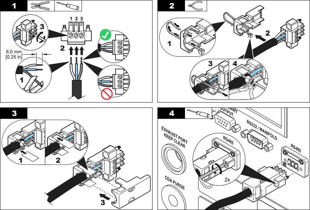
14 Connect to clean dry air (optional) Make sure that all the components installed before the particle counter, including interconnecting lines, are pressure rated for higher than 150 psi. Use a clean dry air (CDA) purge in high vapor areas to minimize contamination of the sensor. The CDA purge typically consists of a pressure source ( psi, 100 psi nominal), a desiccator and an absolute 0.1 µm filter. The CDA will use approximately 0.1 CFM at atmospheric pressure. 2. Switch on the particle counter. 3. Switch on the purge air. Connect RS485 communication (optional) To connect for RS485 communication, refer to the illustrated steps that follow. 1. Connect the purge air line to the CDA purge connector on the particle counter. Refer to Figure 2 on page 9. Use the supplied 1 / 8 - inch NPT fitting. 14 English
15 English 15
16 Particle counter navigation The functions of the particle counter are accessed from the Counter Navigation screen. Table 1 shows the functions that are accessible through the navigation screen. Table 1 Icons - Counter Navigation screen Table 1 Icons - Counter Navigation screen (continued) Icon Function Description Diagnostics View diagnostic information for troubleshooting. Refer to Diagnostics and Troubleshooting on page 19. Icon Function Description Network Configure the network and communication settings. Sample Historical Export Printer Test wizard Locations Group System Measure particle counts. Refer to Measure particle counts on page 16. Review measurement results in the buffer; print, export or filter data. Refer to the expanded manual on the manufacturer's website. Output file as PDF, comma separated value (CSV), tab separated, XML or PortAll files. Refer to the expanded manual on the manufacturer's website. Print sample data as hard-copy. Refer to How to use the Print Center on page 17. Test and report wizard for ISO, EU-GMP, FS or BS classification compliance. Refer to the expanded manual on the manufacturer's website. Add/edit/remove areas; copy location settings, edit locations settings; edit alarms for specific locations. Refer to the expanded manual on the manufacturer's website. Load/add/edit a group; delete a group. Refer to the expanded manual on the manufacturer's website. Time/Date; Sleep time/backlight timeout; set logon requirements; set sounds for alarms; manage users; set the units for flow rates; manage the data buffer. Refer to the expanded manual on the manufacturer's website. Factory Operation Log on to the particle counter Prerequisites Start the system. View the factory information including the calibration date. 1. Activate the backlight with a finger or stylus if needed. 2. Push the icon to log out a previous user. Push again to see the logon screen. 3. Enter the user name and password. Confirm. Note: Push the ALT key to access special characters. Measure particle counts After a complete particle count measurement, the number of particles measured will show on the screen and be stored as data. Other configured parameters, such as relative humidity, temperature and air velocity will be shown and stored in data. 1. Remove the protective cap from the inlet tube on the counter. 2. On the Counter Navigation screen, push SAMPLE. 16 English
17 3. To start the particle count, push. The icon will change to a button while the count is measured. Note: Push to end the test before the count is complete. Incomplete particle count data will not be stored or printed unless the Save Partial Data option is selected in System Settings. 4. When the count measurement is complete, the test will stop automatically. Change the particle count location There are two methods to change the location for a particle count. On the Sample screen, push the location name. Select the new location name and confirm. On the Sample screen, push the PLUS button to increment the location, or push the MINUS button to decrement the location. See settings during the particle count Location and group settings can be seen at any time during the particle count cycle. On the Sample screen, select the Settings tab on the right side of the screen. See historical data during the particle count Historical sample data can be seen at any time during the particle count cycle. 1. On the Sample screen, select the ARROW button. 2. Select the HISTORICAL icon to see the data. Use the filter scan probe N O T I C E The filter scan probe function applies to 1 CFM units only. 1. On the Counter Navigation screen, push SAMPLE. 2. In the Test screen, push. 3. To start the test, push START FILTER PROBE TEST. 4. To end the test, push STOP FILTER PROBE TEST. 5. Push to generate a brief report of the last completed test. How to use the Print Center About the Print Center N O T I C E To avoid damage to the printer, do not operate the printer without paper. If the particle counter must be used without paper, be sure to set the Sample Print Mode field to "None". The particle counter has a built-in printer. The Print Center screen is accessible from the: Counter Navigation screen Historical screen System Diagnostics screen Test/Report Wizard screen Area/Location Setup screen On the Print Center screen, the user can: Set automatic print functions Print buffer records or count averages Note: Filtered data is printed from the Historical screen. Set automatic print functions Note: If the sample period is very brief and the hold time is zero, the sending of some sample data to the printer may be skipped. However, the data is always obtained and saved. To avoid a printout failure, set the total time of the Sample period and the Hold period combined to more than 12 seconds. 1. On the Counter Navigation screen, push PRINTER. 2. On the Print Center screen, select the Sample Print Mode field. Select an option for automatic printing. Option None Description No data will print automatically English 17
18 Option Description Maintenance Alarms Cycles All Prints results at the end of the sample when a count alarm is exceeded Prints the results of multiples of the programmed count cycle. The range is Prints results after each count cycle is finished 3. Set the Cycle Print Order. Options: 10 1 (oldest printed first) or 1 10 (newest printed first). 4. To show the average of the values in the printout when the samples are taken and the data is printed, select Print Averages. Note: The fourth value in the printout is the average of the three previous values. 5. To round values to the nearest whole number, select Round Averages. 6. To repeat the header data on all samples, select Repeat Sample Headers. When not selected, the headers print only with the first sample of a series when the cycles are set to > Push ENTER to confirm. Print records manually The buffer holds 5000 records maximum. The Print Center can print the entire buffer or the average of count cycles obtained at each sample point. To print records manually: 1. On the counter Navigation screen, push PRINTER. 2. On the Print Center screen, select the print option for the data. In the Print Report field, select the regulatory reports that will be printed. 3. The data will begin to print. To cancel the print job, push CANCEL PRINT. To return to Counter Navigation, push RETURN. W A R N I N G Multiple hazards. Do not disassemble the instrument for maintenance. If the internal components must be cleaned or repaired, contact the manufacturer. C A U T I O N Multiple hazards. Only qualified personnel must conduct the tasks described in this section of the document. Clean the instrument exterior The instrument exterior can be cleaned as needed. To avoid human exposure to potentially dangerous chemicals, make sure to clean the touchscreen immediately after contact with chemicals. N O T I C E To prevent damage, do not use an aerosol cleaner or glass cleaner on the touchscreen. Do not leave visible moisture on the instrument or touchscreen. Moisture can penetrate the touchscreen and damage the electronics inside. 1. Put the cap on the sample air intake nozzle to keep contamination out. 2. Spray a mild cleaning solution on a soft cloth. Wipe the outside of the instrument carefully. 3. Use a soft, dry cloth to wipe the touchscreen surface. If needed, moisten the soft cloth with a mild cleaning solution. Set the count to zero Do this procedure after unexpectedly high particle counts. This procedure will verify that the particle counter works correctly and will remove residual particles. 1. Put the zero-count filter on the intake tube. 2. Turn on the unit and log in if needed. 18 English
19 3. Push SAMPLE. 4. Push RUN. 5. Repeat the process until the particle counts return to zero. Charge the batteries in the particle counter Batteries in the particle counter will begin to charge when the AC power adapter is connected. A complete charge in the instrument takes approximately 10 hours. The battery is considered to be fully charged when the battery status light on the front of the instrument shows a charge between 95% and 100%. Prerequisite: Install the batteries in the instrument. Refer to Install the batteries on page 10. N O T I C E Discard the used batteries according to local regulations or contact the manufacturer. Do not put exhausted batteries in the domestic waste. 1. Attach the power supply to the unit. 2. Connect the unit power supply to the external power through the AC power adapter. The battery status light will show the level of power in the battery. Refer to Table 2. Table 2 Battery LED color indications Table 3 System Diagnostics screen example - Clock battery failure Signal Value Status Calibration 0.00 VDC OFF Flow 0.00 VDC OFF Clock battery 0.00 VDC FAIL Battery 1 (bottom) VDC PASS Battery 2 (top) VDC PASS Laser current N/A For troubleshooting that involves technical support from the manufacturer, the user may need to send a fax of the system status printout to technical support. 1. On the Counter Navigation screen, push DIAGNOSTICS. Information about the system, such as serial number and software version, shows. 2. On the Diagnostics screen, push. The printout will show the serial number, date and time and other data about the system. LED state LED color Battery status Charge status Flashing Orange Low power Not charging Flashing Green Low power Charging Solid Green Charged Charging Diagnostics and Troubleshooting The Diagnostics screen shows information that may be needed for troubleshooting. Table 3 shows an example of a failure notification on the Diagnostics screen. English 19
20 Table des matières Caractéristique Détails Caractéristiques à la page 20 Fonctionnement à la page 33 Généralités à la page 21 Maintenance à la page 35 Installation à la page 25 Diagnostics et dépannage à la page 36 Navigation du compteur de particules à la page 33 Informations supplémentaires Des informations supplémentaires sont disponibles sur le site Web du fabricant. Caractéristiques Les caractéristiques techniques peuvent être modifiées sans préavis. Spécifications de l'appareil Caractéristique Exigences électriques Catégorie d installation Classe de protection Niveau de pollution 2 Altitude Source de lumière Type de pompe Affichage du comptage Détails VCA, 3,4 A maximum, Hz à l'alimentation CA vers CC ; 24 VCC et 75 W à l'instrument I III m (6 562 ft) Laser hélium néon, laser de classe 3R (IEC/EN), Laser de classe 3A (CDRH), 5 mw maximum à 632,8 nm A vide d'air, classé pour une utilisation continue Écran tactile couleur ¼ VGA TFT Interface Basé sur Windows CE Comptage maximum affiché 9,999,999 Temps de retard 00:00:06 à 23:59:59 Temps d'échantillonnage et de pause Alarmes de comptage Stockage des données Cycles de comptage 00:00:01 à 23:59:59 Emplacements Jusqu'à 999 Port d'évacuation Sorties Collecteur Protocoles de communication Entrées Purge CDA auto Matériau du boîtier 1 à comptages 50 à échantillons, défilement sur l'écran d'aperçu des Données historiques La valeur par défaut est Jusqu'à 100 en mode automatique 3/8-in. Filetage NPT Ethernet 10Base-T/100Base-TX Série RS485 Série RS232 Sans fil en option b/g compatible Client USB (Version 1.1) USB Hôte (Version 1.1) Auxiliaire (alarme et sonde de balayage) Supports A3432, système de collecteur 32 ports (disponible sur des unités 1 CFM uniquement) Modbus TCP, Modbus RTU, Série FX Sonde de vitesse de l'air, sonde d'humidité/température relative Électrovanne de purge actionnée par le branchement au CDA Acier inoxydable (passivé) 20 Français
21 Caractéristique Poids sans batterie Taille (l x P x H) Environnement, opération Environnement, stockage Certifications Détails 15.9 kg (35 lb) 33 x 56 x 23 cm (13 x 22 x 9 pouces) y compris les saillies, poignées et pieds 0 à 40 C (32 à 104 F) ; 10 à 90 % d'humidité relative sans condensation 40 à 50 C ( 40 à 122 F) ; 0 à 98 % d'humidité relative sans condensation CE, C-Tick, KC, FCC, IC, n d'accession laser CDRH Spécification des batteries Caractéristique Type de batterie Durée de vie de la batterie en fonctionnement Temps de recharge de la batterie Alimentation Détails Batterie intelligente au lithium-ion : peut être chargée, éjectée et remplacée sans interrompre le système. 3 heures minimum 1 6,75 heures minimum, 10 heures maximum 14,4 V cc, 6,6 Ah (2x) Spécifications de mesure de l'échantillon Échantillonnage Gammes de taille des particules et canaux standards Débit Comptage à zéro 0,1 ; 0,2 ; 0,3 ; 0,5 ; 1,0 ; 5,0 µm 28,3 l/min (1,00 cfm) ± 5 % (réglage d'usine par défaut) Conforme à ISO et JIS B comptage ou moins en 5 minutes, niveau de fiabilité à 95% Erreur de coïncidences 5 % à particules/m 3 ( particules/pied 3 ) par méthode ISO Efficacité du comptage 50 % pour 0,1 μm ; 100 % pour 0,15 μm. Entièrement conforme à ISO et JIS B Poids de la batterie 0,66 kg (1,45 lb) 1 Avec deux batteries totalement chargées placées dans une unité de 1.0 CFM (échantillon de 1 m 3 ) échantillonnant pendant 20 minutes, impression d'un rapport, temps de maintien de 5 minutes (simulant un déplacement vers un nouvel emplacement) avant répétition de ce cycle. La temporisation du rétroéclairage est réglée sur deux minutes. Généralités En aucun cas le constructeur ne saurait être responsable des dommages directs, indirects, spéciaux, accessoires ou consécutifs résultant d'un défaut ou d'une omission dans ce manuel. Le constructeur se réserve le droit d'apporter des modifications à ce manuel et aux produits décrits à tout moment, sans avertissement ni obligation. Les éditions révisées se trouvent sur le site Internet du fabricant. Consignes de sécurité A V I S Le fabricant décline toute responsabilité quant aux dégâts liés à une application ou un usage inappropriés de ce produit, y compris, sans toutefois s'y limiter, des dommages directs ou indirects, ainsi que des dommages consécutifs, et rejette toute responsabilité quant à ces dommages dans la mesure où la loi applicable le permet. L'utilisateur est seul responsable de la vérification des risques d'application critiques et de la mise en place de mécanismes de protection des processus en cas de défaillance de l'équipement. Français 21
22 Veuillez lire l'ensemble du manuel avant le déballage, la configuration ou la mise en fonctionnement de cet appareil. Respectez toutes les déclarations de prudence et d'attention. Le non-respect de cette procédure peut conduire à des blessures graves de l'opérateur ou à des dégâts sur le matériel. Assurez-vous que la protection fournie avec cet appareil n'est pas défaillante. N'utilisez ni n'installez cet appareil d'une façon différente de celle décrite dans ce manuel. Interprétation des indications de risques D A N G E R Indique une situation de danger potentiel ou imminent qui, si elle n'est pas évitée, entraîne des blessures graves, voire mortelles. A V E R T I S S E M E N T Indique une situation de danger potentiel ou imminent qui, si elle n'est pas évitée, peut entraîner des blessures graves, voire mortelles. A T T E N T I O N Indique une situation de danger potentiel qui peut entraîner des blessures mineures ou légères. A V I S Indique une situation qui, si elle n'est pas évitée, peut occasionner l'endommagement du matériel. Informations nécessitant une attention particulière. Étiquettes de mise en garde Lisez toutes les informations et toutes les étiquettes apposées sur l appareil. Des personnes peuvent se blesser et le matériel peut être endommagé si ces instructions ne sont pas respectées. Un symbole sur l'appareil est désigné dans le manuel avec une instruction de mise en garde. Si l'appareil comporte ce symbole, reportez-vous au manuel d'utilisation pour consulter les informations de fonctionnement et de sécurité. S'il se trouve sur l emballage d'un produit ou une barrière, ce symbole indique la présence d un danger de choc électrique et/ou d électrocution. Les composants électroniques internes de l'appareil peuvent être endommagés par l'électricité statique, qui risque d'altérer ses performances et son fonctionnement. Ce symbole indique qu'un dispositif laser est utilisé dans l'équipement. Ce symbole indique l emplacement d un fusible ou de tout dispositif de protection contre les surintensités de courant. En Europe, depuis le 12 août 2005, les appareils électriques comportant ce symbole ne doivent pas être jetés avec les autres déchets. Conformément à la réglementation nationale et européenne (Directive 2002/96/CE), les appareils électriques doivent désormais être, à la fin de leur service, renvoyés par les utilisateurs au fabricant, qui se chargera de les éliminer à ses frais. Remarque : Pour le retour à des fins de recyclage, veuillez contactez le fabricant ou le fournisseur d'équipement afin d'obtenir les instructions sur la façon de renvoyer l'équipement usé, les accessoires électriques fournis par le fabricant, et tous les articles auxiliaires pour une mise au rebut appropriée. Conformité Ce symbole indique que l'appareil est un produit LASER de classe Français
23 Il est conforme aux normes IEC/EN :2007 et 21 CFR , à l'exception des écarts prévus dans le cadre de la notice Laser n 50 datée du 24 juin Numéro d'accession FDA : Ce produit est également certifié conforme CE. Contactez le fabricant pour obtenir toutes les informations sur la conformité. Certification Règlement canadien sur les équipements causant des interférences radio, IECS-003, Classe A: Les données d'essai correspondantes sont conservées chez le constructeur. Cet appareil numérique de classe A respecte toutes les exigences du Règlement sur le matériel brouilleur du Canada. Cet appareil numérique de classe A répond à toutes les exigences de la réglementation canadienne sur les équipements provoquant des interférences. FCC part 15, limites de classe A : Les données d'essai correspondantes sont conservées chez le constructeur. L'appareil est conforme à la partie 15 de la règlementation FCC. Le fonctionnement est soumis aux conditions suivantes : 1. Cet équipement ne peut pas causer d'interférence nuisible. 2. Cet équipement doit accepter toutes les interférences reçues, y compris celles qui pourraient entraîner un fonctionnement inattendu. Les modifications de cet équipement qui n ont pas été expressément approuvées par le responsable de la conformité aux limites pourraient annuler l autorité dont l utilisateur dispose pour utiliser cet équipement. Cet équipement a été testé et déclaré conforme aux limites définies pour les appareils numériques de classe A, conformément à la section 15 de la réglementation FCC. Ces limites ont pour but de fournir une protection raisonnable contre les interférences néfastes lorsque l équipement fonctionne dans un environnement commercial. Cet équipement génère, utilise et peut irradier l'énergie des fréquences radio et, s'il n'est pas installé ou utilisé conformément au mode d'emploi, il peut entraîner des interférences dangereuses pour les communications radio. Le fonctionnement de cet équipement dans une zone résidentielle risque de causer des interférences nuisibles, dans ce cas l'utilisateur doit corriger les interférences à ses frais Les techniques ci-dessous peuvent permettre de réduire les problèmes d'interférences : 1. Débrancher l'équipement de la prise de courant pour vérifier s'il est ou non la source des perturbations 2. Si l'équipement est branché sur le même circuit de prises que l'appareil qui subit des interférences, branchez l'équipement sur un circuit différent. 3. Éloigner l'équipement du dispositif qui reçoit l'interférence. 4. Repositionner l antenne de réception du périphérique qui reçoit les interférences. 5. Essayer plusieurs des techniques ci-dessus à la fois. Appareils Wi-Fi A V I S La sécurité du réseau et du point d'accès relève de la responsabilité du client utilisant l'appareil sans fil. Le fabricant ne peut être tenu pour responsable des dommages indirects, particuliers, fortuits ou accessoires occasionnés en raison d'une violation de la sécurité du réseau. Agrément spécifique par pays pour les dispositifs Wi-Fi A T T E N T I O N Risque lié au rayonnement électromagnétique. Assurez-vous que l'antenne se trouve à une distance minimum de 20 cm (7,9 pouces) de l'ensemble du personnel dans des conditions d'utilisation dites normales. L'antenne ne peut pas être colocalisée ou utilisée en combinaison avec une autre antenne ou d'autres transmetteurs. Les produits avec l'option sans fil contiennent un dispositif Wi-Fi modulaire RF fonctionnant dans une gamme de 2,4 GHz. Etats-Unis FCC ID : R68WIPORTG Canada IC ID : 3867A-WIPORT Pays Code à lettres ISO Autriche Belgique AT BA Français 23
24 Pays Code à lettres ISO Danemark DK Finlande FI France FR Allemagne DE Grèce GR Hongrie HU Irlande IE Italie IT Mexique MX Pologne PL Portugal PT Espagne ES Suède SE Royaume Uni GB Islande IS Norvège NO Suisse CH Turquie TR Opinion : Conforme à la directive R&TTE 1999/5/EC sur les exigences essentielles de l' Article 3.2 conformément aux procédures de l' Article 10(5) et Annexe IV for (class-2 équipement) et indiqué comme CE1177. Certification Le produit répond aux exigences de la section 15 de la réglementation FCC et aux normes RSS d'industrie Canada. Le fonctionnement est soumis aux conditions suivantes : 1. Cet équipement ne peut pas causer d'interférence nuisible. 2. Cet équipement doit accepter toutes les interférences reçues, y compris celles qui pourraient entraîner un fonctionnement inattendu. Les modifications de cet équipement de communication sans fil qui n ont pas été expressément approuvées par le responsable de la conformité aux limites pourraient annuler l autorité dont l utilisateur dispose pour utiliser cet équipement. Tout changement apporté à l'équipement annulera la certification d'industrie Canada et l'autorisation FCC. Présentation du produit Cet instrument compte et mesure la taille des particules en suspension dans les environnements des salles blanches. Consulter Spécifications de mesure de l'échantillon à la page 21 pour les plages des tailles des particules. Composants du produit Assurez-vous d'avoir bien reçu tous les composants. Voir Figure 1. Si des éléments manquent ou sont endommagés, contactez immédiatement le fabricant ou un représentant commercial. Pays-Bas NL Agréments des dispositifs de contrôle RF FCC : Approuvé comme dispositif modulaire l'accord de droit TCB. FCC ID : R68WIPORTG IC: Approuvé comme dispositif modulaire sous le Certificat D'Acceptabilité' TechniqueC-REL ID: 3867A-WIPORT 24 Français
25 Figure 1 Composants du produit Installation A V E R T I S S E M E N T Dangers multiples. Seul le personnel qualifié doit effectuer les tâches détaillées dans cette section du document. Information de sécurité du câblage A V E R T I S S E M E N T Risque d'électrocution Assurez-vous de disposer d'un accès facile à la coupure d'alimentation locale. 1 Compteur de particules Clé mémoire USB 2 Batterie rechargeable (2x) ( ) 3 Alimentation CA vers CC ( ) 9 Filtre de comptage à zéro 10 Ensemble connecteur RS485 4 Cordon d'alimentation (américain) 11 Tube rallonge pour capteur isocinétique 5 Cordon d'alimentation (UE) 12 Antenne sans fil pour Wifi 6 Capteur isocinétique 13 Stylet pour interface à écran tactile 7 Rouleaux de papier thermique pour l'imprimante (2x) A V I S Toujours débrancher l'appareil de l'alimentation avant d'effectuer tout branchement électrique. Respectez toutes les mesures de sécurité pendant que l'appareil est branché. Remarques relatives aux décharges électrostatiques A V I S Dégât potentiel sur l'appareil Les composants électroniques internes de l'appareil peuvent être endommagés par l'électricité statique, qui risque d'altérer ses performances et son fonctionnement. Reportez-vous aux étapes décrites dans cette procédure pour éviter d'endommager l'appareil par des décharges électrostatiques. Touchez une surface métallique reliée à la terre (par exemple, le châssis d'un appareil, un conduit ou un tuyau métallique) pour décharger l'électricité statique de votre corps. Evitez tout mouvement excessif. Transportez les composants sensibles à l'électricité statique dans des conteneurs ou des emballages antistatiques. Portez un bracelet spécial relié à la terre par un fil. Travaillez dans une zone à protection antistatique avec des tapis de sol et des sous-mains antistatiques. Français 25
26 Branchements électriques Branchez les capteurs, l'alimentation électrique externe, les câbles et les dispositifs USB tel qu'indiqué au Figure 2 et Figure 3. Figure 3 Vue avant et vue latérale Figure 2 Vue arrière 1 Connecteur RS485 de communication série 6 Raccord de purge CDA (clean dry air : air propre et sec) 2 Connecteur Ethernet 7 Port d'évacuation 1 3 Connecteur d'alimentation 8 Connecteur de contrôleur de collecteur ou port RS232 standard 4 Pied supplémentaire 9 Port E/S auxiliaire pour la sonde de 5 Logements pour batterie balayage du filtre 1 Le port d'évacuation est équipé d'un filetage NPT de 3/8 in. qui peut être connecté à un NPT de 3/8 in. à un adaptateur cannelé pour tube (580854). 1 Buse d'aspiration d'échantillonnage 7 Connecteur hôte USB 2 Ecran tactile 8 Connecteur client USB 3 Bouton d'alimentation 9 Connecteur de sonde d'humidité relative et de température 4 Voyant d'état de la batterie 10 Connecteur de sonde de vitesse de l'air 5 Poignée 11 Antenne sans fil 6 Imprimante Remarque : Pour obtenir de meilleurs résultats, utilisez les clés mémoire USB fournies par le fabricant. 26 Français
27 Sécurité des batteries au lithium A V E R T I S S E M E N T Risque d'incendie et d'explosion. Les batteries au lithium peuvent chauffer, exploser ou prendre feu et provoquer des blessures graves en cas d'exposition à des conditions abusives. N'utilisez pas la batterie si elle apparait endommagée. N'utilisez pas la batterie après un choc fort ou des vibrations importantes. N'exposez pas la batterie à une flamme. Conservez la batterie à des températures inférieures à 60 ºC (140 ºF). Conservez la batterie au sec et à l'abri de l'eau. Evitez que la borne positive et la borne négative de la batterie n'entrent en contact. Ne laissez pas les personnes non autorisées toucher la batterie. Installation des piles A V E R T I S S E M E N T Risque d'explosion. Afin d'éviter tout risque d'incendie/explosion, utilisez le type de batterie et d'alimentation/chargeur spécifiés par le fabricant. Pour les références, reportez-vous à Figure 1 à la page 25. Français 27
28 28 Français
29 Français 29
30 Assemblage du système de compteur de particules Figure 4 explique comment assembler le système de compteur de particules. Figure 4 Assemblage du compteur de particules Consultez les étapes illustrées dans Figure 5 pour installer le papier d'impression. Figure 5 Installation du papier d'impression 1 Installation à distance de la sonde 1 2 Installation locale de la sonde 1 Présentée avec le socle de sonde isocinétique facultatif. Installer le papier d'impression A V I S Afin d'éviter d'endommager l'imprimante, n'utilisez pas cette dernière sans papier. Utilisez uniquement le papier thermique recommandé. Si le compteur de particules doit être utilisé sans papier, assurez-vous de régler le Mode d'impression sur «Aucun». 30 Français
31 Se brancher sur de l'air propre et sec (facultatif) Vérifier que tous les composants installés avant le compteur de particules, y compris les lignes d'interconnexion, supportent une pression supérieure à 150 psi. Utilisez une purge CDA (clean dry air) dans les zones à forte vapeur pour réduire la contamination du capteur. La purge CDA est le plus souvent constituée d'une source de pression ( psi (2,8-8,4 bar), 100 psi nominal (7 bars)), d'un déshydrateur et d'un filtre 0,1 µm absolu. Le CDA consomme environ 0.1 CFM (2,8 L/min) à la pression atmosphérique. 1. Branchez la conduite de purge d'air au raccord de purge CDA sur le compteur de particules. Voir Figure 2 à la page 26. Utilisez le raccord fourni 1 / 8 --pouce NPT. 2. Allumez le compteur de particules. 3. Allumez la purge d'air. Brancher la communication RS485 (facultatif) Pour brancher la communication RS485, consultez les étapes illustrées suivantes. Français 31
32 32 Français
33 Navigation du compteur de particules Les fonctions du compteur de particules sont accessibles depuis l'écran Navigation du compteur. Tableau 1 affiche les fonctions accessibles via l'écran de navigation. Tableau 1 Icônes - écran Navigation du compteur Icône Fonction Description Echantillon Mesurer le comptage de particules. Reportez-vous à Mesure de comptage des particules à la page 34. Tableau 1 Icônes - écran Navigation du compteur (suite) Icône Fonction Description Système Diagnostics Heure/date, temps de veille/temporisation rétroéclairage, définir les conditions de connexion, définir les sons pour les alarmes, gérer les utilisateurs, régler les appareils pour le débit, gérer les données tampon. Consulter le manuel complet sur le site Web du fabricant. Afficher des informations sur les diagnostics pour le dépannage. Voir Diagnostics et dépannage à la page 36. Historique Exporter Imprimante Assistant de test Emplacements Groupe Consulter les résultats de mesure dans la mémoire tampon : imprimer, exporter ou filtrer les données. Consulter le manuel complet sur le site Web du fabricant. Fichier de sortie PDF, de valeurs séparées par des virgules (CSV), séparés par des onglets, XML ou fichiers PortAll. Consulter le manuel complet sur le site Web du fabricant. Imprimer les données d'échantillon sur papier. Voir Comment utiliser le Print Center à la page 34. Assistant de test et de rapport pour conformité de classification ISO, EU-GMP, FS ou BS. Consulter le manuel complet sur le site Web du fabricant. Ajouter/modifier/retirer des zones, copier les réglages d'emplacement, éditer les réglages d'emplacement, éditer les alarmes pour les emplacements spécifiques. Consulter le manuel complet sur le site Web du fabricant. Charger/ajouter/éditer un groupe, supprimer un groupe. Consulter le manuel complet sur le site Web du fabricant. Réseau Usine Fonctionnement Configurer les paramètres du réseau et de communication. Afficher les informations d'usine notamment la date d'étalonnage. Connexion au compteur de particules Actions préalables nécessaires Démarrez le système. 1. Activez le rétro-éclairage avec un doigt ou le stylet si nécessaire. 2. Appuyez sur l'icône pour déconnecter un utilisateur précédent. Appuyez de nouveau sur pour afficher l'écran de connexion. 3. Saisissez le nom d'utilisateur et le mot de passe. Validez. Remarque : Appuyez sur la touche ALT pour accéder aux caractères spéciaux. Français 33
34 Mesure de comptage des particules Après une mesure de comptage complet des particules, le nombre de particules mesurées s'affiche à l'écran et est enregistré dans les données. D'autres paramètres configurés (par exemple, l'humidité relative, la température et la vitesse de l'air) s'affichent et sont enregistrés dans les données. 1. Retirez le capuchon de protection du tube d'entrée du compteur. 2. Sur l'écran de Navigation du compteur, appuyez sur ECHANTILLON. 3. Pour démarrer le compteur de particules, appuyez sur L'icône devient la touche lorsque le comptage est en cours. Remarque : Appuyez sur pour arrêter le test avant la fin du comptage. Les données de comptage de particules incomplètes ne seront pas stockées ou imprimées sauf si l'option Enregistrer les données partielles est sélectionnée dans les Paramètres du système. 4. Lorsque la mesure de comptage est terminée, le test s'arrête automatiquement. Changement d'emplacement du compteur de particules Il existe deux méthodes pour changer l'emplacement d'un compteur de particules. Sur l'écran Echantillon, appuyez sur le nom d'emplacement. Sélectionnez le nom du nouvel emplacement et confirmez. Sur l'écran Echantillon, appuyez sur la touche PLUS pour augmenter l'emplacement ou appuyez sur la touche MOINSpour réduire l'emplacement. Consultation des réglages pendant le comptage de particules Les réglages d'emplacement et de groupe peuvent être visualisés à tout moment pendant le cycle de comptage de particules. Sur l'écran Echantillon, sélectionnez l'onglet Réglages sur le côté droit de l'écran. Consultation des données d'historique pendant le comptage de particules Les données d'échantillon historique peuvent être visualisées à tout moment pendant le cycle de comptage de particules. 1. Sur l'écran Echantillon, sélectionnez la touche FLECHE. 2. Sélectionnez l'icône HISTORIQUE pour afficher les données. Utilisation de la sonde de balayage du filtre A V I S La sonde de balayage du filtre s'applique aux unités 1 CFM uniquement. 1. Sur l'écran de Navigation du compteur, appuyez sur ECHANTILLON. 2. Sur l'écran Test, appuyez sur. 3. Pour lancer le test, appuyez sur DEMARRER LE TEST DE LA SONDE DE FILTRE. 4. Pour arrêter le test, appuyez sur ARRETER LE TEST DE LA SONDE DE FILTRE. 5. Appuyez sur IMPRIMANTE pour créer un bref rapport du dernier test terminé. Comment utiliser le Print Center A propos de Print Center A V I S Afin d'éviter d'endommager l'imprimante, n'utilisez pas cette dernière sans papier. Si le compteur de particules doit être utilisé sans papier, assurez-vous de régler le champ Mode d'impression d'échantillonnage sur "Aucun". Le compteur de particules est équipé d'une imprimante intégrée. L'écran Print Center est accessible depuis : L'écran Navigation du compteur L'écran Historique L'écran Diagnostics du système 34 Français
35 L'écran Assistant de Test/Rapport L'écran Réglage Zone/Emplacement Sur l'écran Print Center, l'utilisateur peut : Régler des fonctions d'impression automatique Imprimer des dossiers en mémoire tampon ou des moyennes de comptage Remarque : Les données filtrées sont imprimées à partir de l'écran Historique. Réglage des fonctions d'impression automatique Remarque : Si la période d'échantillonnage est très courte et que le temps de pause est de 0, certaines données d'échantillon ne seront pas envoyées à l'imprimante. Cependant, les données sont toujours récupérées et enregistrées. Pour éviter un problème d'impression, définissez la durée totale de la période d'échantillonnage et de la période de pause sur plus de 12 secondes. 1. Sur l'écran Navigation du compteur, appuyez sur IMPRIMANTE. 2. Sur l'écran Print Center, sélectionnez le champ Mode d'impression de l'échantillon. Sélectionnez une option pour l'impression automatique. Option None (Aucun) Alarmes Cycles Tous Description Aucune donnée ne sera imprimée automatiquement Imprime les résultats à la fin de l'échantillonnage lorsque l'alarme de comptage est dépassée Imprime les résultats des multiples du cycle de comptage programmé. La plage va de 1 à 99. Imprime les résultats à la fin de chaque cycle de comptage 3. Définissez l'ordre d'impression des cycles. Options : 10-1 (impression la plus ancienne en premier) ou 1-10 (dernière impression en premier). 4. Pour afficher la moyenne des valeurs dans l'impression quand les échantillonnages sont effectués et que les données sont imprimées, sélectionnez Imprimer les moyennes. Remarque : La quatrième valeur de l'impression est la moyenne des trois valeurs précédentes. 5. Pour arrondir les valeurs au nombre entier le plus proche, sélectionnez Arrondir les moyennes. 6. Pour répéter les données d'en-tête sur tous les échantillonnages, sélectionnez Répéter les en-têtes d'échantillonnage. Lorsque cette option n'est pas sélectionnée, les en-têtes sont uniquement imprimés avec le premier échantillonnage d'une série quand les cycles sont définis sur > Appuyez sur ENTREE pour confirmer. Impression manuelle des relevés La mémoire tampon conserve relevés maximum. Le Print Center peut imprimer toute la mémoire tampon ou la moyenne des cycles de comptage obtenue à chaque point d'échantillonnage. Pour imprimer les relevés manuellement : 1. Sur l'écran Navigation du compteur, appuyez sur IMPRIMANTE. 2. Sur l'écran Print Center, sélectionnez l'option d'impression pour les données. Dans le champ Imprimer le rapport, sélectionnez les rapports règlementaires qui seront imprimés. 3. Les données commencent à être imprimées. Pour annuler la tâche d'impression, appuyez sur ANNULER L'IMPRESSION. Pour revenir à l'écran Navigation du compteur, appuyez sur RETOUR. Maintenance A V E R T I S S E M E N T Dangers multiples. Ne démontez pas l'appareil pour l'entretien. Si les composants internes doivent être nettoyés ou réparés, contactez le fabricant. A T T E N T I O N Dangers multiples. Seul le personnel qualifié doit effectuer les tâches détaillées dans cette section du document. Français 35
36 Nettoyage de l'extérieur de l'appareil L'extérieur de l'appareil peut être nettoyé si nécessaire. Afin d'éviter une exposition humaine à des produits chimiques potentiellement dangereux, veuillez nettoyer l'écran tactile immédiatement après le contact avec des produits chimiques. A V I S Pour éviter d'endommager l'appareil, n'utilisez pas de nettoyant en aérosol ou de nettoyant pour vitre sur l'écran. Ne laissez pas de trace d'humidité sur l'appareil ou sur l'écran. L'humidité peut pénétrer à l'intérieur de l'écran tactile et endommager les circuits électroniques à l'intérieur. 1. Mettez le couvercle sur la buse d'aspiration d'échantillonnage pour éviter toute contamination extérieure. 2. Vaporisez une solution nettoyante douce sur un chiffon doux. Frottez soigneusement l'extérieur de l'appareil.. 3. Utilisez un chiffon doux et sec pour essuyer l'écran tactile. Le cas échéant, humidifiez le chiffon doux avec une solution de détergent doux. Réglage du comptage à zéro Appliquez cette procédure à la suite d'un comptage de particules anormalement élevé. Cette procédure permet de vérifier que le comptage de particules fonctionne correctement et d'éliminer les particules résiduelles. 1. Placez le filtre de comptage à zéro sur le tube d'admission. 2. Allumez l'appareil et connectez-vous si nécessaire. 3. Appuyez sur ÉCHANTILLON. 4. Appuyez surexecution. 5. Répétez la procédure jusqu'à ce que le comptage de particules revienne à zéro. Charge des batteries dans le compteur de particules Les batteries commencent à charger lorsque le cordon d'alimentation secteur est branché. La charge complète de l'appareil prend environ 10 heures. On considère que la batterie est entièrement chargée lorsque le voyant d'état de la batterie placé sur le devant de l'instrument affiche un niveau de charge compris entre 95 % et 100 %. Actions préalables nécessaires :installez les batteries dans l'appareil. Voir Installation des piles à la page 27. A V I S Éliminez les batteries usagées conformément aux réglementations locales ou contactez le fabricant. Ne jetez pas les batteries usagées avec les ordures ménagères. 1. Branchez l'alimentation à l'unité. 2. Branchez l'alimentation de l'unité à l'alimentation externe par l'adaptateur d'alimentation secteur. Le voyant d'état de la batterie indique le niveau de puissance de la batterie. Voir Tableau 2. Tableau 2 Indications des couleurs de la LED de la batterie Etat de la LED Couleur du voyant Etat des batteries Etat de charge Clignotant Orange Puissance faible Pas en charge Clignotant Vert Puissance faible Chargement Fixe Vert Chargé Chargement Diagnostics et dépannage L'écran Diagnostics affiche les informations potentiellement nécessaires au dépannage. Tableau 3 présente un exemple de notification de défaillance dans l'écran Diagnostics. Tableau 3 Exemple d'écran Diagnostics du système - Défaillance de la batterie d'horloge Signal Valeur Statut Etalonnage 0,00 V CC DESACTIVE Débit 0,00 V CC DESACTIVE 36 Français
37 Tableau 3 Exemple d'écran Diagnostics du système - Défaillance de la batterie d'horloge (suite) Signal Valeur Statut Batterie horloge 0,00 V CC ECHEC Batterie 1 (bas) 16,42 V CC SUCCES Batterie 2 (haut) 16,44 V CC SUCCES Courant laser N/A Pour le dépannage qui nécessite une assistance technique de la part du fabricant, l'utilisateur peut avoir besoin d'envoyer un fax de l'état du système au support technique. 1. Sur l'écran Navigation du compteur, appuyez sur DIAGNOSTICS. Les informations sur le système, telles que le numéro de série et la version du logiciel, apparaissent. 2. Sur l'écran Diagnostics, appuyez sur L'impression doit indiquer le numéro de série, la date et l'heure ainsi que d'autres informations relatives au système. Français 37
38 目录 规格 详细信息 规格第 38 操作第 50 基本信息第 39 维护第 52 安装第 42 诊断和故障排除第 53 粒子计数器导航第 50 附加信息 制造商网站中提供了附加信息 规格 产品规格如有变化, 恕不另行通知 仪器规格 规格 电源要求 安装类别 保护等级 详细信息 交流 - 直流电源 : V 交流电, 最大 3.4 A,50 60 Hz; 仪器 :24 V 直流电和 75 W I III 污染程度 2 海拔 光源 取样泵类型 计数显示 2000 m (6562 ft) 氦氖激光器,3R 级激光 (IEC/EN),3A 级激光 (CDRH), nm 时最大为 5 mw 真空泵, 适用于连续使用 ¼ VGA TFT 彩色触摸屏 界面基于 Windows 的 CE 显示的最大计数 9,999,999 延迟时间 00:00:06 至 23:59:59 取样和保持时间 00:00:01 至 23:59:59 计数警报 数据存储 1 到 9,999,999 颗 50 到 5000 个样品, 可在 历史数据 审阅屏幕滚动 3000 为默认值 计数周期在自动模式中最多 100 取样点最多 999 排气口 输出 歧管 通信协议 输入 自动 CDA 清洁 3/8 英寸 NPT 螺纹 Ethernet 10Base-T/100Base-TX RS485 串行 RS232 串行 可选无线 兼容 b/g USB 客户端 (1.1 版 ) USB 主机 (1.1 版 ) 辅助 ( 警报和扫描探头 ) 支持 A3432,32 个端口的多支管系统 ( 仅适用于 1 CFM 装置 ) Modbus TCP Modbus RTU 串行 FX 气流速度探头, 相对湿度 / 温度探头 连接 CDA, 激活清洁电磁阀 外壳材料不锈钢 ( 外壳电镀 ) 重量 ( 不含电池 ) 15.9 kg (35 lb) 尺寸 ( 宽 x 长 x 高 ) 33 x 56 x 23 cm (13 x 22 x 9 in.) 包含伸出长度, 手柄和脚撑 操作环境 0 至 40 C(32 至 104 F);10 至 90% 相对湿度, 无冷凝 38 中文
39 规格 详细信息 基本信息 存储环境 40 至 50 C( 40 至 122 F);0 至 98% 相对湿度, 无冷凝 认证 CE,C-Tick,KC,FCC,IC,CDRH 激光准入号 取样测量规格 取样 粒径范围和标准通道 µm 流速 28.3 L/min(1.00 cfm)± 5%( 出厂默认设置 ) 零计数 符合误差 计数效率 电池规格 规格 电池类型 符合 ISO 和 JIS B9921 的规定 1 次计数或少于 5 分钟, 置信度 95% 根据 ISO 方法, 粒子 /m 3 (50000 粒子 /ft 3 ) 时为 5% 50% 为 0.1 μm;100% 为 0.15 μm 完全符合 ISO 和 JIS B 9921 的规定 详细信息 操作期间电池寿命最少 3 小时 1 电池充电时间 电源 电池重量 1 锂离子智能电池 ; 可以充电 弹出和更换, 且不会中断系统 最短 6.75 小时, 最长 10 小时 14.4 VDC,6.6 Ah (2x) 0.66 kg (1.45 lb) 将两块充满电的电池置于 1.0 CFM 仪器中, 进行 20 分钟的取样 (1 m 3 样品 ) 打印记录操作, 再暂停 5 分钟 ( 模拟移至新取样点模式 ), 然后重复此周期 背光超时设置为两分钟 对于因本手册中的任何不足或遗漏造成的直接 间接 特别 附带或结果性损失, 制造商概不负责 制造商保留随时更改本手册和手册中描述的产品的权利, 如有更改恕不另行通知或承担有关责任 修订版可在制造商的网站上找到 安全信息 注意 对于误用和滥用造成的产品损坏, 制造商概不负责, 包括但不限于 : 直接 附带和间接的损坏, 并且对于适用法律允许的最大程度的损坏也不承担任何责任 用户唯一的责任是识别重大应用风险和安装适当的系统, 以在设备可能出现故障时保护流程 请在拆开本设备包装 安装或使用本设备前, 完整阅读本手册 特别要注意所有的危险警告和注意事项 否则, 可能会对操作者造成严重的人身伤害, 或者对设备造成损坏 确保设备提供的保护没有受损 请勿以本手册指定方式之外的其它方式使用或安装本设备 危险信息使用 危险 表示潜在的或紧急的危险情况, 如果不加以避免, 将会导致死亡或严重伤害 警告 表示潜在或非常危险的情形, 如不避免, 可能导致严重的人身伤亡 警告 表示潜在的危险情形, 可能导致一定程度的人身伤害 注意 表明如不加以避免则会导致仪器损坏的情况 需要特别强调的信息 中文 39
40 警告标签 请阅读贴在仪器上的所有标签和标记 如未遵照这些安全标签的指示操作, 则可能造成人身伤害或仪器损坏 仪器上的符号在手册中通过警告说明参考 本符号如果出现在仪器中, 则表示参考说明手册中的操作和 / 或安全信息 仪器外壳或绝缘体上如有此标志, 则表示存在触电或电击致死的风险 静电会损害精密的内部电子组件, 从而导致仪器性能降低或最终出现故障 此标志指示设备中使用激光装置 除了符合 2007 年 6 月 24 日颁布的第 50 号激光公告规定的偏差, 本产品还符合 IEC/EN :2007 和 21 CFR 的规定 FDA 准入号 : 本产品还符合 CE 规定 有关完整的合规详情, 请联系制造商 认证 加拿大无线电干扰产生设备法规 (Canadian Radio Interference- Causing Equipment Regulation),IECS-003,A 类 : 制造商支持测试记录留存 此 A 类数字设备符合加拿大干扰产生设备法规的所有要求 Cet appareil numérique de classe A répond à toutes les exigences de la réglementation canadienne sur les équipements provoquant des interférences. FCC 第 15 部分, A 类限制 制造商支持测试记录留存 该设备符合 FCC 规定第 15 部分的要求 设备操作满足以下两个条件 : 合规 此标志指出保险丝或限流装置的位置 使用此符号标记的电气设备在 2005 年 8 月 12 日后, 不能通过欧洲公共垃圾系统进行处理 为遵守欧洲地区和国家法规 ( 欧盟指令 2002/96/EC), 欧洲电气设备使用者现在必须将废弃或到期的设备送还制造商进行处理, 使用者不必支付任何费用 注 : 如果退回产品是为了进行再循环, 请联系设备生产商或供应商, 索取如何退回使用寿命到期的设备 生产商提供的电源附件以及所有辅助部件的说明, 以便进行适当处理 此标志指示仪器为 1 类激光产品 1. 本设备不会造成有害干扰 2. 本设备必须接受任何接收到的干扰, 包括可能导致意外操作的干扰 若未经负责出具符合声明的一方明确同意擅自对本设备进行改动或改装, 可能会导致取消用户操作该设备的权限 本设备已经过测试, 符合 FCC 规定第 15 部分中确定的 A 类数字设备限制 这些限制专门提供当设备在商业环境下工作时针对有害干扰的合理保护 该设备产生 使用和放射无线电射频能量, 如果不按照说明手册的要求对其进行安装和使用, 可能会对无线电通讯造成有害干扰 本设备在居民区工作时可能会产生有害干扰, 这种情况下用户须自行承担费用消除这种干扰 以下方法可用于减少干扰问题 : 1. 断开设备的电源, 以便确证它是干扰源与否 2. 如果设备与遭受干扰的仪器连接到相同的插座, 将设备连接到其他插座 3. 将设备从接受干扰的仪器边上移开 4. 重新定位受干扰仪器的接收天线 5. 同时尝试以上多项措施 40 中文
41 Wi-Fi 设备 注意 如果用户使用无线仪器, 则有责任确保网络和接入点的安全性 对于因网络安全漏洞引起的任何间接 特殊 附随或从属损失, 制造商概不负责 Wi-Fi 设备的国家特定许可 警告 电磁辐射危险 正常使用时, 确保所有人员与天线保持 20 cm (7.9 in) 的最小距离 天线不能与其它任何天线或发射器放在一起或一同操作 具有无线选项的产品包含在 2.4 GHz 范围内操作的模块式 Wi-Fi 设备 美国 FCC ID:R68WIPORTG 加拿大 IC ID:3867A-WIPORTG 国家 奥地利 比利时 丹麦 芬兰 法国 德国 希腊 匈牙利 爱尔兰 意大利 墨西哥 波兰 葡萄牙 ISO31662 字母代码 AT BA DK FI FR DE GR HU IE IT MX PL PT 国家 西班牙 瑞典 英国 冰岛 挪威 瑞士 土耳其 荷兰 监管 RF 设备审批 ISO31662 字母代码 FCC: 由 TCB Grant of Authorization 批准为模块式设备 FCC ID: R68WIPORTG IC: 由 Certificat D'Acceptabilite' Technique C-REL ID 批准为模块式设备 :3867A-WIPORTG 意见 : 根据 (2 类设备 ) 条款 10(5) 和附录 IV 中的评估步骤, 须符合条款 3.2 基本要求的 R&TTE 指令 1999/5/EC, 并标记为 CE1177 认证 本设备符合 FCC 规定第 15 部分以及加拿大工业部许可豁免 RSS 标准的要求 设备操作满足以下两个条件 : 1. 本设备不会造成有害干扰 2. 本设备必须接受任何接收到的干扰, 包括可能导致意外操作的干扰 若未经负责出具符合声明的一方明确同意, 擅自对本无线通讯设备进行改动或改装, 可能会导致取消用户操作该设备的权限 如果对本设备进行任何更改, 将意味着终止加拿大工业部认证和 FCC 授权 产品概述 该仪器用于计算和测量在洁净室环境中的大气尘粒 参阅取样测量规格第 39 了解粒径范围 ES SE GB IS 否 CH TR NL 中文 41
42 产品组件 确保已收到所有组件 请参阅图 1 如有任何物品丢失或损坏, 请立即联系制造商或销售代表 图 1 产品组件 粒子计数器 8 USB 闪存盘 2 可充电电池 (2x)( ) 9 零计数过滤器 3 交流 - 直流电源 ( ) 10 RS485 插接器 4 电源线 ( 美式 ) 11 采样管 5 电源线 ( 欧式 ) 12 Wi-Fi 无线天线 6 等动力探头 13 用于触摸屏界面的笔针 7 用于打印机的热敏纸卷 (2x) 安装 警告 多种危险 只有合规的专业人员才能从事文件中本部分所述的任务 42 中文
43 接线安全信息 警告 图 2 背面视图 电击致命危险 确保可轻松切断本地电源 注意 进行电气连接前, 务必断开仪器的电源 对仪器进行连接时, 请遵从所有安装声明 静电放电 (ESD) 注意事项 注意 可能导致仪器损坏 静电会损害精密的内部电子组件, 从而导致仪器性能降低或最终出现故障 请参阅此流程中的步骤以防止 ESD 损坏仪器 : 接触接地金属表面 ( 如仪器外壳 金属导管或管道 ), 以将静电排出机壳外 避免过度移动 运送静电敏感的组件时, 请使用抗静电容器或包装 配戴连接到接地线缆的腕带 使用抗静电地板垫和工作台垫, 以使工作区具备静电安全性 电气连接 如图 2 和图 3 所示, 连接探头 外部电源 电缆和 USB 设备 1 串行通信 RS485 接头 6 CDA( 清洁干燥空气 ) 接头 2 以太网接头 7 排气口 1 3 电源接头 8 歧管控制器接头或标准 RS232 端口 4 辅助支脚 9 过滤器扫描探头的辅助 I/O 端口 5 电池端口 1 排气口有一个 3/8 英寸 NPT 螺纹, 可连接至 3/8 英寸 NPT, 连接 3/8 英寸软管倒钩接头 (580854) 中文 43
44 图 3 正面和侧面视图 注 : 为获得最佳结果, 请使用制造商提供的 U 盘 锂电池安全性 警告 火灾和爆炸危险 如果暴露在不当条件下, 锂电池可能变热 爆炸或起火, 并导致严重伤害 如果目视检查发现电池损坏, 切勿使用该电池 如果电池遭受强烈冲击或振动, 切勿使用该电池 请勿将电池投于火中 请将电池保存在温度低于 60 ºC(140 ºF) 的环境中 请保持电池干燥, 防止水损 防止电池正极端子与负极端子相连 切勿允许未经许可的人员触碰电池 1 取样吸气管嘴 7 USB 主机接头 2 触摸屏 8 USB 客户端接头 3 电源按钮 9 相对湿度和温度传感器接头 4 电池状态灯 10 空气流速传感器接头 5 把手 11 无线天线 6 打印机 安装电池 警告 爆炸危险 为避免火灾和 / 或爆炸, 请仅使用制造商指定的电池型号和电源 / 充电器 有关零件编号, 请参阅图 1 第 中文
45 中文 45
46 46 中文
47 组装粒子计数器系统 图 4 显示如何组装粒子计数器系统 参阅图 5 中的图示步骤, 安装打印纸 图 5 安装打印纸 图 4 粒子计数器组装 1 探头的远程安装 1 2 探头的本地安装 1 显示带可选等动力探头架 安装打印纸 注意 为避免损坏打印机, 切勿在没有纸时操作打印机 仅使用推荐的热敏纸 如果粒子计数器必须在没有纸时使用, 请务必将打印模式设置为 无 中文 47
48 连接到清洁干燥空气 ( 可选 ) 确保安装在粒子计数器之前的所有部件 ( 包括互联管 ) 的额定承压能力高于 150 psi 在高压蒸气区使用一个清洁干燥空气 (CDA) 净化装置, 最大程度地降低对传感器的污染 CDA 清洁通常包括压力源 ( 名义上为 psi 100 psi) 干燥器和绝对 0.1 µm 过滤器 在大气压下 CDA 将使用约 0.1 CFM 1. 将吹扫空气管连接到粒子计数器上的 CDA 清洁接头 请参阅图 2 第 43 使用提供的 1 / 8 英寸 NPT 配件 2. 开启粒子计数器 3. 接通净化空气 连接 RS485 通信 ( 可选 ) 如要连接 RS485 通信, 请参阅相关插图和步骤 48 中文
49 中文 49
50 粒子计数器导航 用户可以从 计数器导航 屏幕中访问粒子计数器的功能 表 1 显示通过导航屏幕可访问的功能 表 1 图标 - 计数器导航屏幕 图标功能说明 表 1 图标 - 计数器导航屏幕 ( 续 ) 诊断查看故障排除的诊断信息 请参阅诊断和故障排除第 53 图标功能说明 取样测量粒子计数 请参阅测量粒子计数第 50 网络 配置网络和通信设置 历史 审阅存储器中的测量结果 ; 打印 导出或筛选数据 参阅制造商网站上的扩展手册 工厂 查看包含校准日期的工厂信息 导出 输出文件如 PDF, 逗号分隔值 (CSV), 制表符分隔,XML 或 PortAll 文件 参阅制造商网站上的扩展手册 操作 登录到粒子计数器 打印机打印取样数据作为硬拷贝 请参阅如何使用 打印中心 第 51 先决条件 启动系统 测试向导取样点组系统 ISO EU-GMP FS 或 BS 分类遵从性的测试与报告向导. 参阅制造商网站上的扩展手册 添加 / 编辑 / 移除区域 ; 复制取样点设置 编辑取样点设置 ; 编辑特定取样点的警报 参阅制造商网站上的扩展手册 加载 / 添加 / 编辑组 ; 删除组 参阅制造商网站上的扩展手册 时间 / 日期 ; 睡眠时间 / 背光超时 ; 设置登录要求 ; 设置警报声音 ; 管理用户 ; 设置流速单位 ; 管理数据存储器 参阅制造商网站上的扩展手册 1. 如果需要, 用手指或笔针激活背光 2. 按图标注销先前用户 再按一次出现登录屏幕 3. 输入用户名和密码 确认 注 : 按 Alt 键访问特殊字符 测量粒子计数 完整的粒子计数测量后, 测量到的粒子数目将显示在屏幕上并作为数据存储 相对湿度 温度和空气流速等其他配置的参数将显示并存储在数据中 1. 请取下计数器入口管上的防护帽 2. 在 计数器导航 屏幕上, 按样品 50 中文
51 3. 如要开始粒子计数, 请按 测量计数时, 图标将变为一个 按 钮 注 : 计数结束前, 可按终止测试 除非在 系统设置 中选择了 保存部分数据 选项, 否则不会储存或打印不完整的粒子计数数据 4. 计数测量完成后, 测试将自动停止 更改粒子计数取样点 有两种方法可更改粒子计数的取样点 在 取样 屏幕上, 按取样点名称 选择新取样点名称, 然后确认 在 取样 屏幕上, 按加号按钮以增加取样点, 或按减号按钮以减少取样点 粒子计数期间查看设置 用户可以在粒子计数周期的任何时候查看取样点和组设置 在 取样 屏幕上, 选择屏幕右侧的 设置 选项卡 粒子计数期间查看历史数据 用户可以在粒子计数周期的任何时候查看历史取样数据 1. 在 取样 屏幕上, 按箭头按钮 2. 选择历史数据图标查看该数据 使用过滤器扫描探头 注意 过滤器扫描探头功能仅适用于 1 CFM 装置 1. 在 计数器导航 屏幕上, 按样品 2. 在 测试 屏幕中, 按 3. 要开始测试, 请按启动过滤器探头测试 4. 要结束测试, 请按停止过滤器探头测试 5. 按生成最后完整测试的简要报告 如何使用 打印中心 关于 打印中心 注意 为避免损坏打印机, 切勿在没有纸时操作打印机 如果粒子计数器必须在没有纸时使用, 请务必将 样本打印模式 字段设置为 无 粒子计数器具有内置打印机 用户可以通过以下途径访问 打印中心 屏幕 : 计数器导航 屏幕 历史 屏幕 系统诊断 屏幕 测试 / 报告向导 屏幕 区域 / 取样点设置 屏幕 在 打印中心 屏幕中, 用户可以 : 设置自动打印功能 打印存储器记录或平均计数 注 : 从 历史 屏幕中打印筛选的数据 设置自动打印功能 注 : 如果取样周期非常短且保持时间为零, 可能会跳过某些取样数据发送, 不会将这些取样数据发送至打印机 但是, 所有数据均已被获取且被保存 为避免打印输出故障, 将 取样 周期与 保持 周期的总时间设置为超过 12 秒 1. 在 计数器导航 屏幕上, 按打印机 2. 在 打印中心 屏幕中, 选择 取样打印模式 字段 选择自动打印选项 选项 None( 无 ) 警报 说明 不会自动打印任何数据 计数警报过后, 在取样结束时打印结果 周期打印多个程序化计数周期的结果 范围为 1-99 All( 所有 ) 完成每个计数周期后, 打印结果 中文 51
52 3. 设置 周期打印顺序 选项 :10-1( 先打印最早的 ) 或 1-10( 先打印最新的 ) 4. 在取样或打印数据时, 选择打印平均值即可显示打印输出中的平均值 注 : 打印输出中的第四个值是前三个值的平均值 5. 如要四舍五入取最近的整数值时, 选择取平均值的整数值 6. 如要重复所有样品的头部数据, 选择重复样品头部数据 如未选择, 当周期设置为 > 1 时仅打印一系列中的首个样品的头部数据 7. 按 ENTER 确认 手动打印记录 存储器最多可保留 5000 条记录 打印中心 可打印在每个取样点获取的计数循环平均值或整个存储器数据 手动打印记录 : 1. 在计数器 导航 屏幕, 按打印机 2. 在 打印中心 屏幕中, 选择数据打印选项 在 打印报告 字段, 选择将要打印的管理报告 3. 数据将开始打印 要取消打印作业, 请按取消打印 要返回 计数器导航, 请按返回 注意 切勿在触摸屏上使用喷雾清洁剂或玻璃清洁剂, 以防损坏 切勿在仪器或触摸屏上遗留可见的水分 水分可能渗透触摸屏并损坏内部的电子线路 1. 在样品吸气管嘴上放置一个盖帽以防止污染 2. 在软布上喷洒中性的清洁液 小心擦拭仪器的外部 3. 用柔软干布擦拭触摸屏表面 如果需要, 请用中性的清洁液弄湿软布 将计数设为零 粒子计数异常高后, 请执行此步骤 此步骤将确认粒子计数器是否正常工作, 并将移除剩余粒子 1. 将零计数过滤器放在吸气管上 2. 开启装置并根据需要登录 3. 按取样 4. 按运行 5. 重复此流程, 直到粒子计数恢复零 对粒子计数器中的电池充电 维护 警告 多种危险 请勿拆卸仪器进行维护 如果必须清洁或维修内部组件, 请联系制造商 警告 多种危险 只有合规的专业人员才能从事文件中本部分所述的任务 连接交流电源适配器后, 将会给粒子计数器内的电池充电 在仪器中完全充电需要大约 10 小时 当仪器前部的电池状态灯显示充电量介于 95% 与 100% 之间时, 电池视为完全充电 先决条件 : 将电池装入仪器中 请参阅安装电池第 44 注意 根据本地法规丢弃废旧电池或联系制造商 请勿将用完的电池放入生活垃圾中 1. 将电源连接到装置 2. 使用交流电适配器将装置电源连接到外接电源 电池状态灯将显示电池中的电量级别 请参阅表 2 清洁仪器外部 可以根据需要清洁仪器外部 为了避免人员暴露于潜在危险的化学物质, 请务必在接触化学物质后立即清洁触摸屏 52 中文
53 表 2 电池 LED 指示灯颜色指示 LED 指示灯状态 LED 指示灯颜色 电池状态 充电状态 闪烁 橙色 电池电量低 未充电 闪烁 绿色 电池电量低 充电中 常亮 绿色 充电完毕 充电中 诊断和故障排除 诊断 屏幕会显示故障排除可能需要的信息 表 3 显示 诊断 屏幕上的故障通知示例 表 3 系统诊断 屏幕例示 - 时钟电池故障 信号值 Status( 状态 ) Calibration 0.00 VDC OFF( 关闭 ) 流量 0.00 VDC OFF( 关闭 ) 时钟电池 0.00 VDC FAIL 电池 1( 底部 ) VDC PASS( 正常 ) 电池 2( 顶部 ) VDC PASS( 正常 ) 激光电流 N/A 对于需要制造商提供技术支持的故障排除, 用户可能需要将系统状态打印输出传真给技术支持人员 1. 在 计数器导航 屏幕上, 按诊断 显示系统相关信息, 如序列号, 软件版本 2. 在 诊断 屏幕上, 按 打印输出将显示序列号 日期和时间以及系统的其他数据 中文 53
54
55
 2 11 52 88-320 Fax +49 (0) 2 11 52 88-210 info@hach-lange.")
56 HACH COMPANY World Headquarters P.O. Box 389, Loveland, CO U.S.A. Tel. (970) (800) (U.S.A. only) Fax (970) HACH LANGE GMBH Willstätterstraße 11 D Düsseldorf, Germany Tel. +49 (0) Fax +49 (0) info@hach-lange.de HACH LANGE Sàrl 6, route de Compois 1222 Vésenaz SWITZERLAND Tel Fax Hach Company/Hach Lange GmbH, All rights reserved. Printed in U.S.A.
Lexmark Z600 Series Color Jetprinter
 Z600 Series Color Jetprinter Windows 2003 1 www.lexmark.com 2003 1 LEXMARK INTERNATIONAL, INC. LEXMARK INTERNATIONAL, INC. Lexmark International, Inc., Department F95/032-2, 740 West New Circle Road, Lexington,
Product Specification Chip Intel DSL6540 Thunderbolt 3 Controller Connectors 2 x Thunderbolt 3 ports (Thunderbolt 3 Port 1/Thunderbolt 3 Port 2), supp
, supp") GC-ALPINE RIDGE Installation Guide/ 12WE6-ALPINER-10AR Product Specification Chip Intel DSL6540 Thunderbolt 3 Controller Connectors 2 x Thunderbolt 3 ports (Thunderbolt 3 Port 1/Thunderbolt 3 Port 2),
GC-ALPINE RIDGE Installation Guide/ 12WE6-ALPINER-10AR Product Specification Chip Intel DSL6540 Thunderbolt 3 Controller Connectors 2 x Thunderbolt 3 ports (Thunderbolt 3 Port 1/Thunderbolt 3 Port 2),
* 1 * *1 *2 2
 * 1 * 2 1 2 *1 *2 2 3 1 2 7 bo 8 9 6 5 4 3 bn bm bl bk 1 2 3 * 4 5 6 7 8 9 bk bl p bq bp bm * bn bo bp bq * br br 8 . bs br bq bp bo 1234567 bo bnbm bl 8 9 bk 1 2 3 4 5 6 7 8 9 bk b bl bm bn bo bp
8260
 8260 2004 9 Lenovo 15 32 1 60 40 60 2 ... 6... 6... 7... 9... 11... 14... 15... 15... 16... 17 PictBridge... 18... 19... 19 Lenovo... 21 Lenovo... 23... 24... 25 Lenovo... 28... 29 3 ... 30... 30... 31...
Product Specification Chip Connectors Interface Data Transfer Rate Intel DSL5520 Thunderbolt 2 Controller 2 x Thunderbolt 2 ports (TBT 1/TBT 2), suppo
, suppo") GC-Thunderbolt 2 Installation Guide/ 12WE6-TH2-10AR Product Specification Chip Connectors Interface Data Transfer Rate Intel DSL5520 Thunderbolt 2 Controller 2 x Thunderbolt 2 ports (TBT 1/TBT 2), supporting
GC-Thunderbolt 2 Installation Guide/ 12WE6-TH2-10AR Product Specification Chip Connectors Interface Data Transfer Rate Intel DSL5520 Thunderbolt 2 Controller 2 x Thunderbolt 2 ports (TBT 1/TBT 2), supporting
Caplio R6 Camera User Guide
 G 1 2 3072 2304 1280 (1M) MY SCENE 3 4 t 5 2 6 3 7 N 8 9 10 12 13 3 4 7 2 1 6 5 8 14 2 3 1 16 15 z Z 8 9 6 D t! $ Q " N # F 13 14 4 5 6 11 8 12 9 10 7 15 1 MY SCENE 5 16 1 2 3 4 5 6 7 8 9 28 10 11 12
HP lc200w_UM_Chinese_T_
 lc200w 微 型 生 活 記 錄 器 使 用 說 明 書 目 錄 FCC statement... 5 禁 止 同 置... 6 FCC specific absorption rate (SAR) statement... 6 WEEE 通 知... 6 CE regulatory notice... 6 射 頻 暴 露 信 息 (SAR)- CE... 6 NCC 警 語... 7 電 池
HCD0174_2008
 Reliability Laboratory Page: 1 of 5 Date: December 23, 2008 WINMATE COMMUNICATION INC. 9 F, NO. 111-6, SHING-DE RD., SAN-CHUNG CITY, TAIPEI, TAIWAN, R.O.C. The following merchandise was submitted and identified
Wireless Plus.book
 Seagate Wireless Plus 1AYBA4 Seagate Wireless Plus 2014 Seagate Technology LLC. Seagate Seagate Technology Wave Seagate Media Seagate Technology LLC ipod ipad iphone Time Machine Safari Mac Apple Computer,
Caplio GX100 Camera User Guide
 G 1 2 3 4 t 5 6 3 7 N 8 9 10 12 13 14 2 1 15 16 10 11 9 1 2 3 4 5 6 7 8 9 16 12 13 F 14 15 17 2 15 5 6 VF/LCD ADJ. 7 18 1 3 4 17 18 19 20 21 13 12 z 8 Z 9! $ F O " N # Q 6 D t 16 14 8 9 10 11 1 5 P A
CANVIO_AEROCAST_CS_EN.indd
 简 体 中 文...2 English...4 SC5151-A0 简 体 中 文 步 骤 2: 了 解 您 的 CANVIO AeroCast CANVIO AeroCast 无 线 移 动 硬 盘 快 速 入 门 指 南 欢 迎 并 感 谢 您 选 择 TOSHIBA 产 品 有 关 您 的 TOSHIBA 产 品 的 详 情, 请 参 阅 包 含 更 多 信 息 的 用 户 手 册 () 安
LH_Series_Rev2014.pdf
 REMINDERS Product information in this catalog is as of October 2013. All of the contents specified herein are subject to change without notice due to technical improvements, etc. Therefore, please check
BC04 Module_antenna__ doc
 http://www.infobluetooth.com TEL:+86-23-68798999 Fax: +86-23-68889515 Page 1 of 10 http://www.infobluetooth.com TEL:+86-23-68798999 Fax: +86-23-68889515 Page 2 of 10 http://www.infobluetooth.com TEL:+86-23-68798999
User’s Manual
 SNAP 500 打 印 机 用 户 手 册 1 用 户 手 册 SNAP TM 500 打 印 机 2015 年 8 月 24 日 AVERY DENNISON Manual Edition 2.5 2 SNAP 500 打 印 机 用 户 手 册 WARNING This device complies with Part 15 of the FCC Rules. Operation is subject
HC50246_2009
 Page: 1 of 7 Date: June 2, 2009 WINMATE COMMUNICATION INC. 9 F, NO. 111-6, SHING-DE RD., SAN-CHUNG CITY, TAIPEI, TAIWAN, R.O.C. The following merchandise was submitted and identified by the vendor as:
Microsoft Word - HC20138_2010.doc
 Page: 1 of 7 Date: April 26, 2010 WINMATE COMMUNICATION INC. 9 F, NO. 111-6, SHING-DE RD., SAN-CHUNG CITY, TAIPEI, TAIWAN, R.O.C. The following merchandise was submitted and identified by the vendor as:
HC20131_2010
 Page: 1 of 8 Date: April 14, 2010 WINMATE COMMUNICATION INC. 9 F, NO. 111-6, SHING-DE RD., SAN-CHUNG CITY, TAIPEI, TAIWAN, R.O.C. The following merchandise was submitted and identified by the vendor as:
01CP-WX3030WNetc_CO_ENG.indd
 Data Video Projector User s Manual (Concise) ModelS: 8928A/8930A/8931WA/ 8933W Information in this Guide may change due to product improvements. To obtain the latest manuals, literature, and software please
K301Q-D VRT中英文说明书141009
 THE INSTALLING INSTRUCTION FOR CONCEALED TANK Important instuction:.. Please confirm the structure and shape before installing the toilet bowl. Meanwhile measure the exact size H between outfall and infall
AL-M200 Series
 NPD4754-00 TC ( ) Windows 7 1. [Start ( )] [Control Panel ()] [Network and Internet ( )] 2. [Network and Sharing Center ( )] 3. [Change adapter settings ( )] 4. 3 Windows XP 1. [Start ( )] [Control Panel
入學考試網上報名指南
 入 學 考 試 網 上 報 名 指 南 On-line Application Guide for Admission Examination 16/01/2015 University of Macau Table of Contents Table of Contents... 1 A. 新 申 請 網 上 登 記 帳 戶 /Register for New Account... 2 B. 填
1. 請 先 檢 查 包 裝 內 容 物 AC750 多 模 式 無 線 分 享 器 安 裝 指 南 安 裝 指 南 CD 光 碟 BR-6208AC 電 源 供 應 器 網 路 線 2. 將 設 備 接 上 電 源, 即 可 使 用 智 慧 型 無 線 裝 置 進 行 設 定 A. 接 上 電 源
 1. 請 先 檢 查 包 裝 內 容 物 AC750 多 模 式 無 線 分 享 器 安 裝 指 南 安 裝 指 南 CD 光 碟 BR-6208AC 電 源 供 應 器 網 路 線 2. 將 設 備 接 上 電 源, 即 可 使 用 智 慧 型 無 線 裝 置 進 行 設 定 A. 接 上 電 源 B. 啟 用 智 慧 型 裝 置 的 無 線 Wi-Fi C. 選 擇 無 線 網 路 名 稱 "edimax.setup"
Microsoft Word - Lenovo_L15M3PB2 (Winbook)_3S1P_UN38.3 Test Report_SLEU
_3S1P_UN38.3 Test Report_SLEU") Lithium-ion Battery UN38.3 Test Report Recommendations on the TRANSPORT OF DANGEROUS GOODS (Manual of Tests and Criteria, Fifth revised edition, Amend.2) Customer: Lenovo Model: L15M3PB2 Rating: 11.25V,
Lithium-ion Battery UN38.3 Test Report Recommendations on the TRANSPORT OF DANGEROUS GOODS (Manual of Tests and Criteria, Fifth revised edition, Amend.2) Customer: Lenovo Model: L15M3PB2 Rating: 11.25V,
Important Notice SUNPLUS TECHNOLOGY CO. reserves the right to change this documentation without prior notice. Information provided by SUNPLUS TECHNOLO
 Car DVD New GUI IR Flow User Manual V0.1 Jan 25, 2008 19, Innovation First Road Science Park Hsin-Chu Taiwan 300 R.O.C. Tel: 886-3-578-6005 Fax: 886-3-578-4418 Web: www.sunplus.com Important Notice SUNPLUS
阅 读 提 示 符 号 说 明 禁 止 重 要 注 意 事 项 操 作 使 用 提 示 词 汇 解 释 参 考 信 息 使 用 建 议 DJI 为 Phantom 3 Advanced 用 户 提 供 了 教 学 视 频 和 以 下 文 档 资 料 : 1. 物 品 清 单 2. Phantom 3
 PHANTOM 3 ADVANCED 用 户 手 册 V1.0 2015.04 阅 读 提 示 符 号 说 明 禁 止 重 要 注 意 事 项 操 作 使 用 提 示 词 汇 解 释 参 考 信 息 使 用 建 议 DJI 为 Phantom 3 Advanced 用 户 提 供 了 教 学 视 频 和 以 下 文 档 资 料 : 1. 物 品 清 单 2. Phantom 3 Advanced 用
1.ai
 HDMI camera ARTRAY CO,. LTD Introduction Thank you for purchasing the ARTCAM HDMI camera series. This manual shows the direction how to use the viewer software. Please refer other instructions or contact
LSC操作说明
 1 C H R I S T A L P H A 1-4 LSC 型 Part. No. 102041 A L P H A 2-4 LSC 型 Part. No. 10204 冷 冻 干 燥 机 操 作 说 明 新 研 制 的 LSC-8 控 制 器, 具 备 图 形 显 示 功 能, 能 以 数 据 表 形 式 显 示 参 数, 并 可 选 配 控 制 软 件 LSC-8 1/4 VGA 大 屏 幕
K7VT2_QIG_v3
 ............ 1 2 3 4 5 [R] : Enter Raid setup utility 6 Press[A]keytocreateRAID RAID Type: JBOD RAID 0 RAID 1: 2 7 RAID 0 Auto Create Manual Create: 2 RAID 0 Block Size: 16K 32K
HC70245_2008
 Reliability Laboratory Page: 1 of 6 Date: September 5, 2008 WINMATE COMMUNICATION INC. 9 F, NO. 111-6, SHING-DE RD., SAN-CHUNG CITY, TAIPEI, TAIWAN, R.O.C. The following merchandise was submitted and identified
Microsoft Word - template.doc
 HGC efax Service User Guide I. Getting Started Page 1 II. Fax Forward Page 2 4 III. Web Viewing Page 5 7 IV. General Management Page 8 12 V. Help Desk Page 13 VI. Logout Page 13 Page 0 I. Getting Started
AS4610 Series QSG-EN_SC_TC R02.book
 Quick Start Guide 4/48-Port GE Data Center Switch AS460-0T AS460-0P AS460-54T AS460-54P. Unpack the Switch and Check Contents AS460-0T AS460-0P Note: The switch can also be installed on a desktop or shelf
MODEL COLOR LIST UZ125D2 YMW GRAY YNF RED YRG BLUE 30H WHITE
 MODEL COLOR LIST UZ125D2 YMW GRAY YNF RED YRG BLUE 30H WHITE MODEL COLOR LIST UZ125D2K K13 BLACK YRG BLUE YPK WHITE MODEL COLOR LIST UZ125X2 G22 Q05 GRAY ORANGE GREEN WHITE N28 W08 PREFACE When it becomes
Logitech Wireless Combo MK45 English
 Logitech Wireless Combo MK45 Setup Guide Logitech Wireless Combo MK45 English................................................................................... 7..........................................
Microsoft Word - Lenovo_L14M4P23 (Y51)_4S1P_UN38.3 Test Report_SLEU
_4S1P_UN38.3 Test Report_SLEU") Lithium-ion Battery UN38.3 Test Report Recommendations on the TRANSPORT OF DANGEROUS GOODS (Manual of Tests and Criteria, Fifth revised edition, Amend 1) Customer: Lenovo Model: L14M4P23 Rating: 14.8V,
Lithium-ion Battery UN38.3 Test Report Recommendations on the TRANSPORT OF DANGEROUS GOODS (Manual of Tests and Criteria, Fifth revised edition, Amend 1) Customer: Lenovo Model: L14M4P23 Rating: 14.8V,
A B C D RRC350 RRC Roteo 35/35G
 Roteo 20HV/25H/35/35G User Manual Version 1.2 A B C D 1 4 2 3 6 5 11 10 7 8 9 2 4 6 5 3 7 8 9 1 8 7 6 2 3 9 1 4 5 1 6 3 4 5 2 RRC350 RRC350 1 2 3 4 5 6 7 12 11 5 7 9 3 1 10 4 6 8 13 2 Roteo 35/35G: 12
TX-NR3030_BAS_Cs_ indd
 TX-NR3030 http://www.onkyo.com/manual/txnr3030/adv/cs.html Cs 1 2 3 Speaker Cable 2 HDMI OUT HDMI IN HDMI OUT HDMI OUT HDMI OUT HDMI OUT 1 DIGITAL OPTICAL OUT AUDIO OUT TV 3 1 5 4 6 1 2 3 3 2 2 4 3 2 5
Preface This guide is intended to standardize the use of the WeChat brand and ensure the brand's integrity and consistency. The guide applies to all d
 WeChat Search Visual Identity Guidelines WEDESIGN 2018. 04 Preface This guide is intended to standardize the use of the WeChat brand and ensure the brand's integrity and consistency. The guide applies
8260
 Manual and Pilot Operated Spool Valves 6L Stainless Steel and Brass Bodies /4" to " NPT / / 6/6 Features Ideal for valve automation for the oil and gas market Reliable, robust design with high flow performance
关 于 瓶 装 水, 你 不 得 不 知 的 8 件 事 情 关 于 瓶 装 水, 你 不 得 不 知 的 8 件 事 情 1 水 质 : 瓶 装 的, 不 一 定 就 是 更 好 的 2 生 产 : 监 管 缺 位, 消 费 者 暴 露 于 风 险 之 中 人 们 往 往 假 定 瓶 装 水 是
 关 于 瓶 装 水, 你 不 得 不 知 的 件 事 情 关 于 瓶 装 水, 你 不 得 不 知 的 8 件 事 情 关 于 瓶 装 水, 你 不 得 不 知 的 8 件 事 情 1 水 质 : 瓶 装 的, 不 一 定 就 是 更 好 的 2 生 产 : 监 管 缺 位, 消 费 者 暴 露 于 风 险 之 中 人 们 往 往 假 定 瓶 装 水 是 干 净 安 全 健 康 的, 广 告 传 递
OA-253_H1~H4_OL.ai
 WARNINGS Note: Read ALL the following BEFORE using this product. Follow all Guidelines at all times while using this product. CAUTION This warning indicates possibility of personal injury and material
ebook140-8
 8 Microsoft VPN Windows NT 4 V P N Windows 98 Client 7 Vintage Air V P N 7 Wi n d o w s NT V P N 7 VPN ( ) 7 Novell NetWare VPN 8.1 PPTP NT4 VPN Q 154091 M i c r o s o f t Windows NT RAS [ ] Windows NT4
 Table of Contents Power Film Capacitors Power Film Capacitors Series Table Product Type Series Voltage Capacitance() Page DC-Link Power Film Capacitors Power Film Capacitors Power Film Capacitors Power
Applied Biosystems StepOne™ Real-Time PCR System Quick Reference Card for Installation
 Applied Biosystems StepOne Real-Time PCR System StepOne 系统安装 快速参考卡 本文档提供在并置布局中安装 StepOne 系统的简明指导 有关 完整步骤或独立安装步骤 请参阅 Applied Biosystems StepOne Real-Time PCR System 安装 联网和维护指南 目录 1. 安装准备........................................
HOIE WITH PREISION is also the Easy choice! Easy-Laser Easy-Laser
 E915 1 HOIE WITH PREISION is also the Easy choice! Easy-Laser Easy-Laser SIMPLE ND EFFETIVE Easy-Laser D23 Easy-Laser E5 TEHNIL DT System Relative humidity 10 95% (complete system) 12.1 kg [26.7 lbs] arrying
DR2010.doc
 DR/2010 HACH 11-8-96-2 HACH. DR/2010, / UL E79852 CSA C22.223 LR 58275 VDE GS 1015-92 FCC"A" 15 : AMADOR CORP, HACH. EN50 011/CISPR 11 "B" (EMI)/89/336/EEC/EMC: AMADOR CORP, HACH.. EN50 082-1( )/89/226/EEC
HC20093A_2008
 Reliability Laboratory Page: 1 of 6 Date: March 5, 2008 KORENIX TECHNOLOGY., CO. FL 9, NO. 100-1, MIN-CHUAN RD. SHING TIEN CITY, TAIPEI, TAIWAN The following merchandise was submitted and identified by
 THE INSTLLING INSTRUCTION FOR CONCELED TNK Important instuction:.. Please confirm the structure and shape before installing the toilet bowl. Meanwhile measure the exact size H between outfall and infall
Cube20S small, speedy, safe Eextremely modular Up to 64 modules per bus node Quick reaction time: up to 20 µs Cube20S A new Member of the Cube Family
 small, speedy, safe Eextremely modular Up to 64 modules per bus de Quick reaction time: up to 20 µs A new Member of the Cube Family Murrelektronik s modular I/O system expands the field-tested Cube family
HC70044_2008
 Page: 1 of 9 Date: July 10, 2008 KORENIX TECHNOLOGY CO., LTD. 9 F, NO. 100-1, MING-CHUAN RD., SHIN TIEN CITY, TAIPEI, TAIWAN The following merchandise was submitted and identified by the vendor as: Product
Guide to Install SATA Hard Disks
 SATA RAID 1. SATA. 2 1.1 SATA. 2 1.2 SATA 2 2. RAID (RAID 0 / RAID 1 / JBOD).. 4 2.1 RAID. 4 2.2 RAID 5 2.3 RAID 0 6 2.4 RAID 1.. 10 2.5 JBOD.. 16 3. Windows 2000 / Windows XP 20 1. SATA 1.1 SATA Serial
Panaboard Overlayer help
 Panaboard Overlayer Image Capture Software for Electronic Whiteboard (Panaboard) ... 3... 5... 6... 13...14 Panaboard Overlayer 1. 2. 3. 4. 4-1. 4-2. [ / ] ( ) 4-3. 5. 6. 6-1. 6-2. [ / ] ( ) 7. Panaboard
 DOC022.80.80343 DR 1900 02/2014, 版 本 1 用 户 手 册 目 录 规 格...3 基 本 信 息...4 安 全 信 息...4 危 险 信 息 使 用...4 警 告 标 签...4 认 证...4 产 品 概 述...5 产 品 组 件...5 安 装...6 安 装 电 池...6 安 装 样 品 池 适 配 器...7 安 装 保 护 盖...7 用 户
Lexmark Prospect Pro200 Series 快速参考手册
 Lexmark Prospect Pro200 Series 快 速 参 考 手 册 2009 年 4 月 www.lexmark.com 有 关 打 印 墨 盒 回 收 的 重 要 信 息! 请 在 打 开 您 的 打 印 墨 盒 包 装 盒 之 前 仔 细 阅 读 以 下 内 容 Lexmark 始 终 认 真 地 履 行 着 保 护 环 境 的 承 诺, 并 且 我 们 鼓 励 我 们 的 用
Product Type Batteries (only) Circuit Breatkers & Load Protection Connection Devices Contactors Ethernet Switches, Stratix Switches I/O Modules; PLC N
 Circuit Breatkers & Load Protection Connection Devices Contactors Ethernet Switches, Stratix Switches I/O Modules; PLC N") 1201 South Second Street Milwaukee, Wisconsin U.S.A. 53204 Tel 414-382-2000 1 July 2016 RE: China Restriction of Hazardous Substances (RoHS) Dear Customer, Rockwell Automation is committed to demonstrating
1201 South Second Street Milwaukee, Wisconsin U.S.A. 53204 Tel 414-382-2000 1 July 2016 RE: China Restriction of Hazardous Substances (RoHS) Dear Customer, Rockwell Automation is committed to demonstrating
CONGRATULATIONS ON YOUR PURCHASE OF OUR CAMERA This product has been carefully inspected through rigid quality control before shipment. With reasonabl
 INSTRUCTIONS MANUAL SMOKE DETECTOR COLOR, B/W CCD CAMERA CONTENTS English / Chinese PREFACE SAFETY INSTRUCTIONS FUNCTION DESCRIPTION INSTALLATION SPECIFICATIONS PR0210SDE2 Thank you very much for purchasing
WFC40810
 9000086873 (PD 85 05 10) Operating and Installation Instructions Please read this specification carefully before you use the product. Any failure and losses caused by ignoring the above mentioned items
KDC-U5049 KDC-U4049 Made for ipod, and Made for iphone mean that an electronic accessory has been designed to connect specifically to ipod, or iphone,
 KDC-U5049 KDC-U4049 Made for ipod, and Made for iphone mean that an electronic accessory has been designed to connect specifically to ipod, or iphone, respectively, and has been certified by the developer
Pin Configurations Figure2. Pin Configuration of FS2012 (Top View) Table 1 Pin Description Pin Number Pin Name Description 1 GND 2 FB 3 SW Ground Pin.
 Table 1 Pin Description Pin Number Pin Name Description 1 GND 2 FB 3 SW Ground Pin.") Features Wide 3.6V to 32V Input Voltage Range Output Adjustable from 0.8V to 30V Maximum Duty Cycle 100% Minimum Drop Out 0.6V Fixed 300KHz Switching Frequency 12A Constant Output Current Capability Internal
Features Wide 3.6V to 32V Input Voltage Range Output Adjustable from 0.8V to 30V Maximum Duty Cycle 100% Minimum Drop Out 0.6V Fixed 300KHz Switching Frequency 12A Constant Output Current Capability Internal
68369 (ppp quickstart guide)
") Printed in USA 04/02 P/N 68369 rev. B PresencePLUS Pro PC PresencePLUS Pro PresencePLUS Pro CD Pass/Fails page 2 1 1. C-PPCAM 2. PPC.. PPCAMPPCTL 3. DB9D.. STPX.. STP.. 01 Trigger Ready Power 02 03 TRIGGER
Printed in USA 04/02 P/N 68369 rev. B PresencePLUS Pro PC PresencePLUS Pro PresencePLUS Pro CD Pass/Fails page 2 1 1. C-PPCAM 2. PPC.. PPCAMPPCTL 3. DB9D.. STPX.. STP.. 01 Trigger Ready Power 02 03 TRIGGER
安全防范
 8989 Be Right TM Sigma 900 5/03 2003 ...1...4...8 1.1...8 1.2...9 1.2.1...9 1.2.2...12 1.3...12 1.4...12 1.4.1...12 1.4.2...13 1.4.3...14 1.5...15 1.6...16 1.7...16 1.7.1...17 1.7.2...17 1.7.3...18 1.7.4
HC80279_2007
 Reliability Laboratory Page: 1 of 7 Date: August 31, 2007 TEMWELL CORPORATION 8F-1, NO. 51, SEC. 1, MIN SHENG E. RD., TAIPEI, TAIWAN The following merchandise was submitted and identified by the vendor
E15-3D1 1. Specifications Compact 4-Way Cassette type Model name MMU- AP0071MH2UL AP0091MH2UL AP0121MH2UL AP0151MH2UL AP0181MH2UL Cooling Capacity kbt
 E15-3D1 Compact 4-Way Cassette type MMU-AP0071MH2UL MMU-AP0091MH2UL MMU-AP0121MH2UL MMU-AP0151MH2UL MMU-AP0181MH2UL Contents 1. Specifications 2. Dimensions 3. Center of gravity 4. Piping diagram 5. Wiring
Microsoft Word - SupplyIT manual 3_cn_david.doc
 MR PRICE Supply IT Lynette Rajiah 1 3 2 4 3 5 4 7 4.1 8 4.2 8 4.3 8 5 9 6 10 6.1 16 6.2 17 6.3 18 7 21 7.1 24 7.2 25 7.3 26 7.4 27 7.5 28 7.6 29 7.7 30 7.8 31 7.9 32 7.10 32 7.11 33 7.12 34 1 7.13 35 7.14
Rotary Switch Catalogue
 Rotary Switches RS300/400/500 Series Outline Our RS series embody the manufacturing history of our company. All series are sturdy and solid with high dependability designed for control units of plants,
Product Type Batteries (only) Circuit Breakers & Load Protection Connection Devices Contactors Ethernet Switches, Stratix Switches I/O Modules; PLC Ne
 Circuit Breakers & Load Protection Connection Devices Contactors Ethernet Switches, Stratix Switches I/O Modules; PLC Ne") 1201 South Second Street Milwaukee, Wisconsin U.S.A. 53204 Tel 414-382-2000 1 July 2016 RE: China Restriction of Hazardous Substances (RoHS) Dear Customer, Rockwell Automation is committed to demonstrating
1201 South Second Street Milwaukee, Wisconsin U.S.A. 53204 Tel 414-382-2000 1 July 2016 RE: China Restriction of Hazardous Substances (RoHS) Dear Customer, Rockwell Automation is committed to demonstrating
P3PC-1342-01ZH
 fi-5530c P3PC-1342-01ZH fi-5530c 目 录 规 则 信 息... ii 注 意 事 项, 责 任... iii 安 全 注 意 事 项... v 第 一 章 准 备 扫 描 仪... 1 1.1 检 查 包 装 箱 中 的 内 容... 1 1.2 各 部 件 名 称 及 功 能... 1 1.3 操 作 面 板... 2 第 二 章 安 装 扫 描 仪... 3 2.1
untitled
 (100V 120V 220V 230V) i ii ! (Return Lead) iii iv 1....... 1 1-1.... 1 1-2.... 2 2..... 4 3..... 3-1.... 3-2.... 3-3....... 4..... 9 5......... 5-1.LCD..... 5-2.... 5-3.... 5-4.... 6..... 6-1.... 6-2....
WVT new
 Operating and Installation Instructions 5120 004601 (PD 84 09 25) Please read this specification carefully before you use the product. Any failure and losses caused by ignoring the above mentioned items
Gerolor Motors Series Dimensions A,B C T L L G1/2 M8 G1/ A 4 C H4 E
 Gerolor Motors Series Size CC-A Flange Options-B Shaft Options-C Ports Features 0 0 12 12 1 1 0 0 2 2 31 31 0 0 SAE A 2 Bolt - (2) 4 Bolt Magneto (4) 4 Bolt Square (H4) 1.0" Keyed (C) 2mm Keyed (A) 1.0'
Building Technology Experience Center concept air conditioning concept heat pump special energy-saving techniques in hydraulics Concrete core conditio
 Building Technology Experience Center concept air conditioning concept heat pump special energy-saving techniques in hydraulics Concrete core conditioning Initial situation Passive House Technology Experience
Microsoft Word - LR1122B-B.doc
 UNISONIC TECHNOLOGIES CO., LTD LOW NOISE ma LDO REGULATOR DESCRIPTION The UTC is a typical LDO (linear regulator) with the features of High output voltage accuracy, low supply current, low ON-resistance,
iPod shuffle 功能指南
 1 1 3 4 4 5 6 7 2 9 9 itunes 10 itunes 12 13 16 3 19 19 4 21 21 Apple Earphones 22 Dock 22 ipod USB Power Adapter 22 5 23 26 6 27 27 29 7 30 2 1 ipod shuffle 1   podcast Internet  itunes Store audible.com
(Guangzhou) AIT Co, Ltd V 110V [ ]! 2
![(Guangzhou) AIT Co, Ltd V 110V [ ]! 2](/thumbs/50/25954686.jpg "(Guangzhou) AIT Co, Ltd V 110V [ ]! 2") (Guangzhou) AIT Co, Ltd 020-84106666 020-84106688 http://wwwlenxcn Xi III Zebra XI III 1 (Guangzhou) AIT Co, Ltd 020-84106666 020-84106688 http://wwwlenxcn 230V 110V [ ]! 2 (Guangzhou) AIT Co, Ltd 020-84106666
(Guangzhou) AIT Co, Ltd 020-84106666 020-84106688 http://wwwlenxcn Xi III Zebra XI III 1 (Guangzhou) AIT Co, Ltd 020-84106666 020-84106688 http://wwwlenxcn 230V 110V [ ]! 2 (Guangzhou) AIT Co, Ltd 020-84106666
Microsoft PowerPoint - ATF2015.ppt [相容模式]
![Microsoft PowerPoint - ATF2015.ppt [相容模式]](/thumbs/72/67494642.jpg "Microsoft PowerPoint - ATF2015.ppt [相容模式]") Improving the Video Totalized Method of Stopwatch Calibration Samuel C.K. Ko, Aaron Y.K. Yan and Henry C.K. Ma The Government of Hong Kong Special Administrative Region (SCL) 31 Oct 2015 1 Contents Introduction
Improving the Video Totalized Method of Stopwatch Calibration Samuel C.K. Ko, Aaron Y.K. Yan and Henry C.K. Ma The Government of Hong Kong Special Administrative Region (SCL) 31 Oct 2015 1 Contents Introduction
ebook140-9
 9 VPN VPN Novell BorderManager Windows NT PPTP V P N L A V P N V N P I n t e r n e t V P N 9.1 V P N Windows 98 Windows PPTP VPN Novell BorderManager T M I P s e c Wi n d o w s I n t e r n e t I S P I
V39用户手册0227.doc
 300 2004 (FCC) FCC I/O B Cet appareil numérique de la classe B respecte toutes les exigences du Réglement sur le matériel brouilieur du Canada. Windows Windows 98 Windows 2000 Windows ME Windows XP Microsoft
WTO
 10384 200015128 UDC Exploration on Design of CIB s Human Resources System in the New Stage (MBA) 2004 2004 2 3 2004 3 2 0 0 4 2 WTO Abstract Abstract With the rapid development of the high and new technique
Chapter 2
 2 (Setup) ETAP PowerStation ETAP ETAP PowerStation PowerStation PowerPlot ODBC SQL Server Oracle SQL Server Oracle Windows SQL Server Oracle PowerStation PowerStation PowerStation PowerStation ETAP PowerStation
Microsoft Word - Atmel-45136A-Pick-Best-Microcontroller-Strom-Eiland-Flodell_Article_CS
 如 何 为 您 的 下 一 款 设 计 选 出 最 好 的 8 位 或 32 位 微 控 制 器 作 者 : Atmel 产 品 营 销 高 级 总 监 Oyvind Strom Atmel 产 品 营 销 总 监 Andreas Eieland Atmel 研 发 工 具 部 门 高 级 产 品 营 销 经 理 Henrik Flodell 不 久 之 前, 嵌 入 式 系 统 还 是 既 昂 贵
Windows XP
 Windows XP What is Windows XP Windows is an Operating System An Operating System is the program that controls the hardware of your computer, and gives you an interface that allows you and other programs
2015 Chinese FL Written examination
 Victorian Certificate of Education 2015 SUPERVISOR TO ATTACH PROCESSING LABEL HERE Letter STUDENT NUMBER CHINESE FIRST LANGUAGE Written examination Monday 16 November 2015 Reading time: 11.45 am to 12.00
Microsoft Word - LD5515_5V1.5A-DB-01 Demo Board Manual
 Subject LD5515 Demo Board Model Name (5V/1.5A) Key Features Built-In Pump Express TM Operation Flyback topology with PSR Control Constant Voltage Constant Current High Efficiency with QR Operation (Meet
712s
 Vickers Filters Target-Pro 11/95 712-C ............................................................... 3............................................................... 4...............................................................
Sony Ericsson Mobile Communications AB
 SAR Information FCC Statement Declaration of Conformity Sony Ericsson U1 UMTS HSPA Band 1/8 GSM GPRS/EDGE 850/900/1800/1900 English Radio wave exposure and Specific Absorption Rate (SAR) information This
Gerotor Motors Series Dimensions A,B C T L L G1/2 M G1/ A 4 C H4 E
 Gerotor Motors Series Size CC-A Flange Options-B Shaft Options-C Ports Features 0 0 5 5 1 0 1 0 3 3 0 0 SAE A 2 Bolt - (2) 4 Bolt Magneto (4) 4 Bolt Square (H4) 1.0" Keyed (C) 25mm Keyed (A) 1.0' 6T Spline
nf4 sli infinity 87100526S 1.p65
 935-CK804A-044 87100526S 2 FCC and DOC Statement on Class B This equipment has been tested and found to comply with the limits for a Class B digital device, pursuant to Part 15 of the FCC rules. These
Symantec™ Sygate Enterprise Protection 防护代理安装使用指南
 Symantec Sygate Enterprise Protection 防 护 代 理 安 装 使 用 指 南 5.1 版 版 权 信 息 Copyright 2005 Symantec Corporation. 2005 年 Symantec Corporation 版 权 所 有 All rights reserved. 保 留 所 有 权 利 Symantec Symantec 徽 标 Sygate
Microsoft Word - 301E高温样本封面.doc
 无锡卓尔阀业有限公司 301E 三偏心高温 蝶阀 Triple Eccentric High Temperature Butterfly Valves STANDARD SPECIFICATION 301E GENERAL 301E Triple Eccentric High Temperature Butterfly valve 301E Triple eccentric high temperature
Front 2 Polar F11 ( ) : Polar F11 Polar F11 Polar F11 Polar (Keeps U Fit - Own Workout Program) Polar Polar F11 Polar F11 Polar F11 Polar (
 : Polar F11 Polar F11 Polar F11 Polar (Keeps U Fit - Own Workout Program) Polar Polar F11 Polar F11 Polar F11 Polar (") Front 1 - Polar F11 Light OK Back Front 2 Polar F11 ( ) : Polar F11 Polar F11 Polar F11 Polar (Keeps U Fit - Own Workout Program) Polar Polar F11 Polar F11 Polar F11 Polar (www.polarfitnesstrainer.com)
Front 1 - Polar F11 Light OK Back Front 2 Polar F11 ( ) : Polar F11 Polar F11 Polar F11 Polar (Keeps U Fit - Own Workout Program) Polar Polar F11 Polar F11 Polar F11 Polar (www.polarfitnesstrainer.com)
Chn 116 Neh.d.01.nis
 31 尼 希 米 书 尼 希 米 的 祷 告 以 下 是 哈 迦 利 亚 的 儿 子 尼 希 米 所 1 说 的 话 亚 达 薛 西 王 朝 二 十 年 基 斯 流 月 *, 我 住 在 京 城 书 珊 城 里 2 我 的 兄 弟 哈 拿 尼 和 其 他 一 些 人 从 犹 大 来 到 书 珊 城 我 向 他 们 打 听 那 些 劫 后 幸 存 的 犹 太 人 家 族 和 耶 路 撒 冷 的 情 形
ch_code_infoaccess
 地 產 代 理 監 管 局 公 開 資 料 守 則 2014 年 5 月 目 錄 引 言 第 1 部 段 數 適 用 範 圍 1.1-1.2 監 管 局 部 門 1.1 紀 律 研 訊 1.2 提 供 資 料 1.3-1.6 按 慣 例 公 布 或 供 查 閱 的 資 料 1.3-1.4 應 要 求 提 供 的 資 料 1.5 法 定 義 務 及 限 制 1.6 程 序 1.7-1.19 公 開 資
8260
 ASCO Stainless Steel Spool Valves Manually Operated and Main Supply Reset Valves Pilot Operated 316L Stainless Steel Bodies 1/4" NPT 3/2 Features Ideal for oil and gas control panel applications Drop-in
 NAIS-500 AIS B 简体中文 www.bandg.com www.simrad-yachting.com www.lowrance.com Navico NAIS-500 AIS B NAVICO HOLDING Navico Holding AS 2017 Navico Holding AS ¼ / / NAIS-500 1 1 4 4 4 7 AIS B 7 AIS 8 8 9 12
On/Off/ FlexiClip HFC FlexiClip
 zh-hk M.-Nr. 09 715 890 ... 7... 19... 20... 21 On/Off/... 22... 22... 23... 24... 24... 26... 27... 27... 27... 27... 27... 28... 28 FlexiClip HFC72... 29 FlexiClip... 29... 34... 34... 34... 34... 34...
2 2 3 DLight CPU I/O DLight Oracle Solaris (DTrace) C/C++ Solaris DLight DTrace DLight DLight DLight C C++ Fortran CPU I/O DLight AM
 C/C++ Solaris DLight DTrace DLight DLight DLight C C++ Fortran CPU I/O DLight AM") Oracle Solaris Studio 12.2 DLight 2010 9 2 2 3 DLight 3 3 6 13 CPU 16 18 21 I/O DLight Oracle Solaris (DTrace) C/C++ Solaris DLight DTrace DLight DLight DLight C C++ Fortran CPU I/O DLight AMP Apache MySQL
Oracle Solaris Studio 12.2 DLight 2010 9 2 2 3 DLight 3 3 6 13 CPU 16 18 21 I/O DLight Oracle Solaris (DTrace) C/C++ Solaris DLight DTrace DLight DLight DLight C C++ Fortran CPU I/O DLight AMP Apache MySQL
THIS DEVICE COMPLIES WITH PART 15 OF THE FCC RULES. OPERATION IS SUBJECT TOTHE FOLLOWING TWO CONDITIONS: (1) THIS DEVICE MAY NOT CAUSE HARMFUL INTERFE
 THIS DEVICE MAY NOT CAUSE HARMFUL INTERFE") GM-R04 Gaming Mouse User s Manual Model(s): GM-R04 www.gigabyte.com.tw THIS DEVICE COMPLIES WITH PART 15 OF THE FCC RULES. OPERATION IS SUBJECT TOTHE FOLLOWING TWO CONDITIONS: (1) THIS DEVICE MAY NOT CAUSE
GM-R04 Gaming Mouse User s Manual Model(s): GM-R04 www.gigabyte.com.tw THIS DEVICE COMPLIES WITH PART 15 OF THE FCC RULES. OPERATION IS SUBJECT TOTHE FOLLOWING TWO CONDITIONS: (1) THIS DEVICE MAY NOT CAUSE
LTTH-product-bro
 海 南 海 航 汉 莎 技 术 培 训 有 限 公 司 培 训 课 程 介 绍 飞 机 维 修 培 训 课 程 海 航 汉 莎 培 训 产 品 产 品 选 择 培 训 目 标 海 南 海 航 汉 莎 技 术 培 训 有 限 公 司 是 于 2007 年 由 德 国 汉 莎 技 术 培 训 和 海 航 集 团 共 同 出 资 建 立 的 一 家 专 门 从 事 民 用 航 空 维 修 培 训 的 中
UTI (Urinary Tract Infection) - Traditional Chinese
 - Traditional Chinese") UTI (Urinary Tract Infection) Urinary tract infection, also called UTI, is an infection of the bladder or kidneys. Urethra Kidney Ureters Bladder Vagina Kidney Ureters Bladder Urethra Penis Causes UTI
UTI (Urinary Tract Infection) Urinary tract infection, also called UTI, is an infection of the bladder or kidneys. Urethra Kidney Ureters Bladder Vagina Kidney Ureters Bladder Urethra Penis Causes UTI
Ác Åé å Serial ATA ( Sil3132) S A T A (1) SATA (2) BIOS SATA (3)* RAID BIOS RAID (4) SATA (5) SATA (a) S A T A ( S A T A R A I D ) (b) (c) Windows XP
 S A T A (1) SATA (2) BIOS SATA (3)* RAID BIOS RAID (4) SATA (5) SATA (a) S A T A ( S A T A R A I D ) (b) (c) Windows XP") Serial ATA ( Sil3132)...2 (1) SATA... 2 (2) B I O S S A T A... 3 (3) RAID BIOS RAID... 6 (4) S A T A... 10 (5) S A T A... 12 Ác Åé å Serial ATA ( Sil3132) S A T A (1) SATA (2) BIOS SATA (3)* RAID BIOS
Serial ATA ( Sil3132)...2 (1) SATA... 2 (2) B I O S S A T A... 3 (3) RAID BIOS RAID... 6 (4) S A T A... 10 (5) S A T A... 12 Ác Åé å Serial ATA ( Sil3132) S A T A (1) SATA (2) BIOS SATA (3)* RAID BIOS
1756-IN610B-ZH-P,ControlLogix Remote I/O (RIO) 模块,安装说明
 模块,安装说明") 安 装 说 明 ControlLogix Remote I/O (RIO) 模 块 产 品 目 录 号 1756-RIO/B 主 题 页 码 重 要 用 户 须 知 2 环 境 和 机 柜 3 防 止 静 电 放 电 4 带 电 插 拔 5 北 美 危 险 场 所 认 证 6 关 于 模 块 8 开 始 之 前 的 工 作 10 模 块 组 件 11 电 源 要 求 12 安 装 模 块 12 检
安 装 说 明 ControlLogix Remote I/O (RIO) 模 块 产 品 目 录 号 1756-RIO/B 主 题 页 码 重 要 用 户 须 知 2 环 境 和 机 柜 3 防 止 静 电 放 电 4 带 电 插 拔 5 北 美 危 险 场 所 认 证 6 关 于 模 块 8 开 始 之 前 的 工 作 10 模 块 组 件 11 电 源 要 求 12 安 装 模 块 12 检