CVN B365M GAMING PRO V20.doc
|
|
|
- 再 庞
- 4 years ago
- Views:
Transcription
1 CVN B365M GAMING PRO V20
2 CVN B365M GAMING PRO V20 目录 第一章简介 主板特色 主板规格 主板布局图... 3 第二章硬件安装 基本硬件安装 跳线设置 连接器和引脚插针 背板接口介绍 第三章驱动程序安装说明 第四章 BIOS 设置 进入 BIOS 主界面 BIOS 主界面 系统信息 (Main) 高级 BIOS 设置 (Advanced) 芯片组设置 (Chipset) 安全设置 (Security) 启动设置 (Boot) 超频设置 (C.Oclock)...25 Chapter 5 English Introduction ntroduction Hardware Installation BIOS Setting...43

3 根据中华人民共和国信息产业部发布的 电子信息产品污染控 制管理办法 所展开的 SJ/T 标准要求, 本产品污染控制标识 以及有毒有害物质或元素标识说明如下 : 产品有毒有害物质或元素标识 : 产品中有毒有害物质或元素的名称及含量 部件名称 有毒有害物质或元素铅 (Pb) 汞 (Hg) 镉 (Cd) 六价铬多溴联苯多溴二苯醚 (Cr(VI)) (PBB) (PBDE) PCB 板 结构件 芯片 连接器 被动电子元器件 焊接金属 线材 助焊剂, 散热膏, 标签以及其他耗材 : 表示该有毒有害物质在该部件所有均质材料中的含量均在 SJ/T 标准规定 的限量要求以下 : 表示该有毒有害物质至少在该部件的某一均质材料中的含量超出 SJ/T 标准规定的限量要求 备注 : 位置的铅的含量超出 ST/T 标准规定的限量要求, 但符合欧盟 RoHS 指令的豁免条款
4 版权 本手册版权属于世和资讯公司所有, 未经本公司书面许可, 任何人不得对此说明书和其中所包含的任何资料进行复制 拷贝或翻译成其它语言 声明 本用户手册没有任何形式的担保 立场表达或其它暗示 若有任何因本用户手 册或其所提到之产品的所有信息, 所引起直接或间接的数据流失 利益损失或事业终止, 七彩虹及其所属员工恕不为其担负任何责任 除此之外, 本用户手册所提到的产品规格及信息仅供参考, 内容亦会随时升级, 恕不另行通知 本用户手册的所有部分, 包括硬体及软体, 若有任何错误, 七彩虹没有义务为其担负任何责任 商标版权 本手册使用的所有商标均属于该商标的持有者所有 AMD, Athlon, Athlon XP, Thoroughbred 和 Duron 是 Advanced Micro Devices 的注册商标 Intel 和 Pentium 是 Intel Corporation 的注册商标 PS/2 和 OS 2 是 International Business Machines Corporation 的注册商标 Windows 95/98/2000/NT/XP/Vista 是 Microsoft Corporation 的注册商标 Netware 是 Novell, Inc 的注册商标 Award 是 Phoenix Technologies Ltd 的注册商标 AMI 是 American Megatrends Inc 的注册商标 Kensington 和 MicroSaver 是 Kensington Technology Group 的注册商标 PCMCIA 和 CardBus 是 Personal Computer Memory Card International Association 的注册商标 其他在本说明书中使用的产品名称是他们各自所属公司所拥有和被公认的 技术支持如果您的系统出现问题, 并且无法从本主板使用手册中获得帮助, 请联系您所购买主板的经销商 此外您还可以尝试通过以下方式获得帮助 :
 获取产品和驱动程序等信息支持, 还可以登录七彩虹官方论坛 (http://bbs.colorful.")
5 访问七彩虹的官方网站 ( 获取产品和驱动程序等信息支持, 还可以登录七彩虹官方论坛 ( 获取技术指导 通过拨打 客户服务热线进行咨询, 此外还可以直接与七彩虹各属 地平台服务中心联系, 具体联系方法如下 : 七彩虹科技全国区域售后服务平台业务范围及联系方式 平台名称 服务范围 联系方法 北京服务平台 北京 天津 河北 河南 山东 山西 内蒙古 沈阳服务平台 辽宁 吉林 黑龙江 武汉服务平台 湖北 湖南 江西 南京服务平台 江苏 安徽 浙江 上海服务平台 上海 广州服务平台 广东 广西 福建 海南 成都服务平台四川 重庆 云南 贵州 西藏 西安服务平台陕西 甘肃 宁夏 青海 新疆 深圳服务平台深圳地区 注意 : 以上电话如有变动, 请拨打 服务热线查询 世和资讯公司对本手册拥有最终解释权
6 在您开始之前 主板包装盒内附标准组件 在您打开本主板包装盒之后, 请马上检查下面所列出的各项标准配件是否齐全 1 块 CVN B365M GAMING PRO V20 主板 2 条 SATA 6Gb/s 数据线 1 张驱动光盘 1 片后置面板 IO 档板 1 本主板中英文使用手册 注意 : 以上配件仅供参考, 请以实物为准, 七彩虹科技保留修改的权利 Note: 若以上列出的任何一项配件有损坏的情形, 请尽快与您的经销 商联络或致电七彩虹客服 注意 : 产品规格 /CPU 支持 / 产品附件以产品发布之时为准
7 第一章简介 感谢您购买七彩虹主板, 该主板提供了非常优越的性能和品质保证 1-1 主板特色 CVN B365M GAMING PRO V20 主板采用 Intel B365 芯片组, 支持 Intel LGA1151 Coffee Lake-S 系列处理器, 支持双通道 DDR4-2666/2400/2133MHz 内存条 主板提供 4 个 DDR4 内存条插槽 1 个 HDMI 接口 1 个 DVI 接口 6 个 SATA3.0 接口 板载 8 声道声卡 集成千兆网卡, 性能强劲, 是性价比的终极选择! 主板提供 1 个 PCI Express3.0x1 插槽 1 个 PCI Express3.0x16 插槽 1 个 PCI Express3.0x4 插槽 2 个 M.2 插槽 1 个 WiFi / BT 模块插槽, 扩展模式丰富, 扩展性能强劲 1-2 主板规格 设计 matx 板型规范 芯片组 主板采用 Intel B365 高速芯片组 中央处理器 支持 Intel LGA1151 Coffee Lake-S 系列处理器 温馨提示 : 当使用 95W CPU 时, 请搭配标准 95W 或 95W 以上散热器! 内存 提供 4 个内存条插槽, 支持 XMP 内存 支持双通道 DDR4-2666/2400/2133MHz 内存条 扩展插槽 1 个 PCI Express 3.0x1 插槽 1 个 PCI Express 3.0x16 插槽 1 个 PCI Express 3.0x4 插槽 1 个 WiFi / BT 模块插槽 2 个 M.2 插槽 ( 支持 PCI-e x4 SSD, 支持 NVME 规范, 支持 Intel OPTANE 技术 ) 1
8 CVN B365M GAMING PRO V20 存储设备 主板提供 6 个 SATA3.0 6Gb/s 硬盘接口 8 声道音频设备 整合 8 声道高清晰数字音频控制器 支持 8 声道 3D 环绕声效 网络功能 主板采用千兆网卡 支持 10/100/1000Mbps 数据传输率 USB 接口 主板提供 6 个 USB2.0 和 6 个 USB3.1Gen1 接口 (5xTYPE-A+1xTYPE-C)( 含扩展 ) 板载连接头 / 跳线 / 按钮 1 个前置音频接口插针 (F_AUDIO) 1 个前面板开关机和指示灯插针 (FPANEL) 2 个 USB2.0 接口扩展插针 (FUSB1,FUSB2) 1 个 USB3.1 Gen1 接口扩展插针 (F_SUSB3_1) 3 个风扇插座 (CFAN1, CFAN2, SFAN1) 1 个喇叭插针 (SPEAK) 1 个数字音频插针 (JSPDIF1) 1 个 COM 插针 (JCOM) 1 个清 COMS 跳线插针 (JBAT) 2 个 RGB 风扇插针 (RGB1, RGB2) 1 个 ME 插针 (JME) 2
9 1-3 主板布局图 ( 仅供参考 ) 3
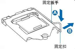
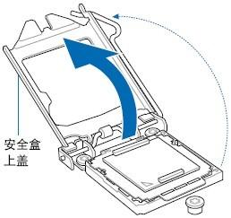
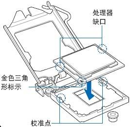
10 第二章 硬件安装 请参照以下步骤, 完成电脑的安装 : 安装中央处理器 (CPU) 安装内存 装入机箱 安装所有扩展卡 连接所有讯号线 排线 电源线及面板控制线 2-1 基本硬件安装 安装中央处理器和风扇 本主板具备一个 Socket 1151 处理器插槽, 本插槽是专为 Intel LGA1151 接口 Coffee Lake-S 系列处理器所设计 请依照以下步骤安装处理器和风扇 : 1. 找到位于主板上的处理器插槽, 将 CPU 插座旁的锁定杆从锁定状态 拔到未锁定状态 2. 安装 CPU, 将 CPU 的金色三角形标示对准主板 CPU 插槽上的三角形 标示, 确定针角 1 的方向正确, 不要用力插 CPU, 确信 CPU 完全插入插槽中, 将锁定杆从未锁定状态拔到锁定状态 ( 这一过程非常重要, 如 果操作不当, 有可能会损坏 CPU, 所以最好请专业人士代劳 ) 3. 安装 CPU 风扇, 并将 CPU 风扇电源线连接上 请注意, 一定要安装 CPU 风扇, 否则可能会温度过高从而损坏 CPU, 建议用户使用原装风扇 4
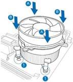
11 5
12 CVN B365M GAMING PRO V20 安装内存 主板提供 4 个 DDR4 内存条插槽 下图所示为 DDR4 内存条插槽在主板上 的位置 一条内存 : 你可以插入到任何一个内存条插槽 两条内存 : 插入到 DIMM1 和 DIMM3 插槽, 或 DIMM2 和 DIMM4 插槽, 以组建双通道. 三条内存 : 不要安插 3 条内存, 可能会引起故障 四条内存 : 插入到 DIMM1 DIMM2 DIMM3 DIMM4 插槽 CAUTION: 1. 请选择使用相同的内存模组安装到双通道 2. 如果您正确插入了内存模组, 您将不会看到金手指部分 安装显卡主板提供 1 个 PCI Express 3.0x16 插槽 1 个 PCI Express 3.0x4 插槽, 用于安装显卡 安装时, 将显卡垂直压入插槽中, 直到其牢固固定于插槽中为止 PCIExpress3.0x16 插槽, 支持 x16 运行规格 (PCIEX16) PCIExpress3.0x1 插槽 PCIExpress3.0x4 插槽, 支持 x4 运行规格 (PCIEX4) 6


13 2-2 跳线设置 CMOS 清除插针 :JBAT 此跳线可以清除主板的 CMOS 资料 ( 例如 : 日期及 BIOS 设定 ), 回到出厂设定值 如果您要清除 CMOS 资料, 请使用跳线帽短接该跳线的针脚数秒钟 注意 : 1. 清除 CMOS 资料前, 请先关闭计算机并拔除电源线 2. 清除 CMOS 资料后在启动计算机前, 请记得移除两针脚间的跳线帽, 否则会造成主板的损坏 2-3 连接器和引脚插针 电源连接器 :ATXPWR,PWR12V 在与电源适配器相连时, 请务必确认, 电源适配器的接头安装方向正确, 针脚对应顺序也准确无误 8-Pin 电源接口用于为 CPU 供电 注意 : 如果要安装功率消耗较大的硬件设备, 请使用高功率的电源 7
14 CVN B365M GAMING PRO V20 前面板开关机和指示灯插针 :FPANEL PWR_ON:ATX 电源开关 短接此引脚可以开机 RST: 重启开关 短接此引脚, 不需关闭系统电源即可重新启动计算机 PWR_LED: 电源指示灯 当系统电源开启时, 此灯会亮起 HD_LED: 硬盘指示灯 对硬盘进行数据存取时, 此灯会亮起 SATA 端口连接器 : 主板提供 6 个 SATA3.0 6Gb/s 硬盘接口 8
15 WIFI/BT 模块插槽 :M.2_WIFI 主板提供 1 个 WIFI/BT 模块插槽, 支持 2230 尺寸规格的 WiFi /BT 模块 M.2 插槽 主板提供 2 个 M.2 插槽, 支持 PCI-e x4 SSD, 支持 NVME 规范, 支持 Intel OPTANE 技术 两个 M.2 插槽都支持 2242/2260/2280 尺寸规格的 SSD, 数据传输率最高可达 32Gb/s IntelOPTANE 技术是 Intel 最新推出的非易失性存储技术, 是一种介于传统内存 固态硬盘之间, 性能极高, 延迟极低的技术 当使用 Intel OPTANE 技术时,M.2 插槽需使用 Intel 专用 OPTANE SSD, 安装 WIN10 64bit 系统和 RST 驱动,BIOS 设置中也要开启 Intel OPTANE 技术选项 请依下列步骤将 M.2 SSD 正确地安装于插槽 : 1. 请用螺丝起子依序将螺丝和螺柱拆下, 将实际要安装的 M.2 SSD 找到适合螺丝孔位之后, 先锁上螺柱 2. 将 M.2 SSD 以斜角方式放入插槽 3. 压住 M.2 SSD 之后, 再将螺丝锁上 9

16 CVN B365M GAMING PRO V20 前置音频接口插针 :F_AUDIO 您可以在前置面板接口上连接一个音频接口, 它是和 I/O 前置面板连接规格兼容的 USB2.0 接口扩展插针 :FUSB1,FUSB2 主板提供 2 个 USB2.0 连接头, 可扩展至 4 个 USB2.0 接口 USB2.0 接口传输速率最高可达到 480Mbps, 可以提供高速的互联网连接 互动式电脑游戏, 还可以同时运行高速的外围设备 10
 将串口模组的排线连 接至这个插座,")
17 USB3.1 Gen1 接口扩展插针 :F_SUSB3_1 主板提供 1 个 USB3.1 Gen1 连接头, 可扩展至 2 个 USB3.1 Gen1 接口 USB3.0 数据传输速率最高可达到 5Gb/s 可向下兼容 USB 设备 串行设备插针 :JCOM 主板提供 1 个 COM 连接头, 用来连接串口 (COM) 将串口模组的排线连 接至这个插座, 接着将该模组安装至机箱后侧面板空的插槽中 11
18 CVN B365M GAMING PRO V20 RGB 风扇插针 :RGB1, RGB2 主板提供 2 个 RGB 风扇插针 安装时, 连接线上有箭头标识的方向, 要对准插座的第一针脚 ( 即 PCB 板上标识为 12V 的针脚 ) 在 BIOS 选项中, 可以设置风扇灯的颜色, 祥细请参照 BIOS 设置 风扇插座 :CFAN1,CFAN2,SFAN1 主板共提供 3 个风扇插座, 用来降低 CPU 和系统的温度 其中 CFAN1 和 CFAN2 是 CPU 风扇插座, 连接 CPU 风扇, 用来降低 CPU 温度 12
19 SPDIF 插针 :JSPDIF1 这组排针是用来连接 SPDIF 数码音频模组, 您可以利用这组排针以 SPDIF 音频数据线连接到音频设备的数码音频输出端, 使用数码音频输出来代替常规的模拟音频输出 关于连接方法请参照适配卡的使用手册 2-4 背板接口介绍 后置面板提供丰富的输入和输出接口 主板背板接口包括 :PS2 鼠标和键盘通用端口 USB2.0 接口 HDMI 接口 DVI 接口 USB3.1 Gen1 TYPE-A 接口 USB3.1 Gen1 TYPE-C 接口 千兆网络接口 1 组 6 孔八声道音频接口 13
 驱动光盘能自动检测主板所使用的芯片组型号 声卡型号 板载显卡型号或者板载网卡型号, 点击相应的按钮安装相应的驱动")
20 第三章驱动程序安装说明 插入七彩虹主板驱动程序安装光盘, 安装程序会自动运行, 弹出下面窗口 CAUTION: 安装完成硬件后, 必须安装对应的驱动程序, 才能发挥主板的强劲性能 ( 请以实物为准 ) 驱动光盘能自动检测主板所使用的芯片组型号 声卡型号 板载显卡型号或者板载网卡型号, 点击相应的按钮安装相应的驱动 14
21 第四章 BIOS 设置 该章介绍如何通过 BIOS 设置来更改系统设置, 详细内容请参考此章 该章包含下列内容 : Main( 系统信息 ) Advanced( 高级 BIOS 设置 ) Chipset( 高级芯片组特征 ) Security( 安全设置 ) Boot( 启动设置 ) C.Oclock( 超频设置 ) CAUTION: 由于主板的 BIOS 版本在不断的升级, 所以, 本手册中有关 BIOS 的描述仅供参考 4-1 进入 BIOS 主界面 本章提供了 BIOS Setup 程序的信息, 让用户可以自己配置优化系统设置 如下情形您需要运行 SETUP 程序 : Note: 1. 系统自检时屏幕上出现错误信息, 并要求进入 SETUP 程序 2. 您想根据客户特征更改出厂时的默认设置 进入设定程序在计算机启动时,BIOS 进入开机自检 (Post) 程序, 自检程序是一系列固定在 BIOS 中的诊断程序, 当自检程序执行完成后, 显示出如下信息 : Press DEL to enter Setup. ( 按 DEL > 键即可进入 SETUP) 如果此信息在您做出反应前就消失了, 您可以关机后再开机或按机箱上的 Reset 键, 重启您的电脑, 也可以同时按下 <Ctrl> + <Alt>+<Delete> 来重启电脑 15
22 控制键位 < > 向前 向后移动选项 < > 向左 向右移动选项 < Enter > 选定此选项 < Esc > 退出菜单或者从子菜单回到主菜单 < +/PU > 增加数值或改变选择项 < -/PD > 减少数值或改变选择项 < F1 > 主题帮助, 仅在状态显示菜单和选择设定菜单有效 < F7 > 恢复前次的 CMOS 设定值, 仅在选择设定菜单时有效 < F9> 载入优化缺省值 < F10 > 保存改变后的 CMOS 设定值并退出 主板 BIOS 支持鼠标操作 Main Advanced Chipset Security Boot C.Oclock BIOS Information BIOS Vendor Core Version Compliancy Project Version Build Date and Time Access Level ME FW Version Total Memory System Language System Date System Time American Megatrends 5.12 UEFI 2.7;PI 1.6 KBL0E /25/ :00:47 Administrator MB English 03/07/ : 22: 49 Select Screen /Click:Select Item Enter/ Dbl Click: Select +/-: Change Opt F1: General Help F7: Previous Values F9: Optimized Defaults F10: Save & Exit ESC: Exit Version Copyright (c) 2019 American Megatrends,Inc 进入 setup 程序之后, 第一个屏幕就是主菜单 16
23 主菜单 主菜单显示了 BIOS 所提供的设定项目类别 您可使用方向键选择不同的条目 对选定项目的提示信息显示在屏幕的底部 子菜单 如果你发现在左边某一区域有向右的指针符号 ( 如上图所示 ), 这就意味此项附加了子菜单 选中此项, 按下回车即可进入此选项子菜单 然后您可以使用控制键在子菜单直接移动并改变设定值 回到主菜单, 按下 <Esc> 主题帮助 BIOS 设定程序提供了帮助屏幕 你可以通过简单地按下 <F1> 键从任何菜单中调出此帮助屏幕 此帮助屏幕列出了相应的键和可能的选择项目 按下 <Esc> 退出帮助屏 4-2 BIOS 主界面 Main( 系统信息 ) 使用此菜单可对基本的系统配置进行设定, 例如时间, 日期 Advanced( 高级 BIOS 设置 ) 使用此菜单可对系统的高级特征进行设定 Chipset( 芯片组设置 ) 使用此菜单可以对芯片进行相应的设定 Security( 安全设定 ) 使用此菜单可以对 BIOS 密码进行相应的设定 Boot( 启动设置 ) 使用此菜单可以对计算机启动设备进行相应的设定 C.Oclock( 超频设置 ) 使用此菜单可以对 CPU/ 芯片组以及内存进行超频, 优化系统的性能表现 17
24 CVN B365M GAMING PRO V 系统信息 (Main) System Language( 语言 ) 设置 BIOS 的语言界面 设定值有 : 英语 中文简体 韩语 System Date( 日期 ) 设置日期, 格式为 < 月 >< 日 >< 年 > Month 月份, 从 Jan.( 一月 ) 到 Dec.( 十二月 ) Date 日期, 从 1 到 31 可用数字键修改 Year 年, 用户设定年份 System Time( 时间 ) 设置时间, 时间格式为 < 时 >< 分 >< 秒 > 4-4 高级 BIOS 设置 (Advanced) Main Advanced Chipset Security Boot C.Oclock CPU Configuration SATA And RST Configuration Power Management Configuration ACPI Settings Super IO Configuration Hardware Monitor USB Configuration CSM Configuration Select Screen Up/Down:Choose Item Enter/ Click: Select +/-: Change Opt F1: General Help F7: Previous Values F9: Optimized Defaults F10: Save & Reset ESC: Exit Version Copyright (c) 2019AmericanMegatrends,Inc 18
25 CPU Configuration(CPU 设置 ) Intel(VMX) Virtualization Technology 开启或关闭 Intel 虚拟化技术 Intel 虚拟化技术让您可以在同一平台的独立 数据分割区, 执行多个操作系统和应用程序 设定值有 :Disabled Enabled Intel(R) Speed Shift Technology 开启或关闭 Intel 变速技术 设定值有 :Disabled Enabled Active Processor Cores 设置激活处理器核心个数 C states 开启或关闭 CPU C 状态功能 设定值有 :Disabled Enabled SATA And RST Configuration(SATA 和 RST 功能设置 ) SATA Controller(S) 开启或关闭 SATA 控制器 设定值有 :Enabled Disabled SATA Mode Selection 设置 SATA 接口的工作模式 设定值有 :AHCI RAID/Optane SATA Controller Speed 设置 SATA 接口运行的速度 设定值有 :Default Gen1 Gen2 Gen3 SATA 1-6 显示 SATA1-6 接口的连接状态 Power Management Configuration( 电源设置 ) EUP Function 设置是否开启 EUP 节能功能 设定值有 :Disabled Enabled 当开启 PS/2 鼠标 / 键盘唤醒和 USB 鼠标 / 键盘唤醒时, 此选项需设置为 Disabled USB KB/MS Wakeup Function 设置 USB 键盘 / 鼠标唤醒功能 设定值有 :Disabled Enabled Wake By Lan 设置网络唤醒 设定值有 :Disabled Enabled 19
26 CVN B365M GAMING PRO V20 Power On By PS/2 Keyboard 设置 PS/2 键盘开机 设定值有 :Disabled AnyKey( 任意键 ) Password ( 密码 ) Power On By PS/2 Mouse 设置 PS/2 鼠标开机 设定值有 :Disabled Enabled AC Power Loss 设置断电后再来电,PC 的状态 设定值有 :Power On( 开机 ) Power Off ( 关机 ) Last State( 上次断电时的状态 ) Wake system from S5 设置系统唤醒 设定值有 :Disabled Fixed Time( 定时 ) Dynamic Time ( 动态时间 ) 选择 Fixed Time 时, 会弹出具体唤醒时间的设置 以小时 / 分 / 秒的格式来表示 各项目合理的范围是 :Hour/ 时 (0-23), Minute/ 分 (0-59), Second/ 秒 (0-59) Red LED Control 设置 RGB 风扇灯颜色为红色 设定值有 :Disabled Enabled Green LED Control 设置 RGB 风扇灯颜色为绿色 设定值有 :Disabled Enabled Blue LED Control 设置 RGB 风扇灯颜色为蓝色 设定值有 :Disabled Enabled ACPI Settings(ACPI 高级配置 ) Enable ACPI Auto Configuration 设置 ACPI 自动配置 设定值有 :Disabled Enabled 选择 Enabled, 则 ACPI 会打开所有支持的睡眠模式 ; 选择 Disabled, 则会弹出以下选项 : Enable Hibernation 开启或关闭操作系统睡眠功能 此选项仅对部分操作系统有效 设定值有 : Disabled Enabled ACPI Sleep State 选择 OS 下待机模式 设定值有 :Suspend Disabled S3(Suspend to RAM) 20
27 Super IO Configuration( 超级 IO 设置 ) PS/2 Port Setting 设置 IO 接口 PS2 运行模式 设定值有 :Auto( 自动 ) KeyBoard(PS2 键盘 ) Mouse(PS2 鼠标 ) Serial Port Configuration 点击 Serial Port Configuration 选项, 将出现以下两个子选项 : Serial Port 启动和关闭串口控制器 设定值有 :Disabled Enabled Change Settings( 更改设置 ) 此选项用来改变串口地址 Hardware Monitor( 硬件监控 ) CPU / SYS Temperature 显示当前 CPU/ 系统 的温度 CPU Fan1/ CPU Fan2 Speed 显示当前 CPU 风扇 1/CPU 风扇 2 运行的速度 CPU VOL/DIMM VOL 显示当前 CPU 电压 / 内存电压 CPU Smart FAN Controller 开启或关闭 CPU 风扇智能运行 设定值有 :Disabled Enabled USB Configuration(USB 设置 ) Legacy USB Support 设置开启或关闭传统 USB 设备功能 传统 USB 就是老的 1.1USB 设备,USB 键盘和鼠标都属于传统 USB 使用 USB 键盘和鼠标时, 此选项需设置为 Enabled 设定值有:Enabled Disabled Auto XHCI Hand-off 本项目用来启动支持没有 XHCI hand-off 功能的操作系统 设定值有 : Disabled Enabled USB Mass Storage Driver Support 设置 USB 大容量存储器支持 设定值有 :Disabled Enabled 21
28 CVN B365M GAMING PRO V20 Port 60/64 Emulation USB 端口 60/64 仿真设置 当此功能被启用时,USB 键盘可以输入一些特殊的组合键 设定值有 :Disabled Enabled USB transfer time-out 此选项设定 USB2.0 总线上一数据传输的最长时间, 如果在此时间内传输没有完成, 则报错给 EFI 此设置仅作用于 EFI, 对 OS 下 USB 驱动无作用 设定值有 :1 Sec 5 Sec 10 Sec 20 Sec Device reset time-out 此选项设定 USB2.0 总线上存储设备复位所需的最长时间 在此时间内, EFI 会检查存储设备是否可以接受指令 如果超时, 则认为存储设备出错 设定值有 :10 Sec 20 Sec 30 Sec 40 Sec Device power-up delay 此选项设定 USB 设备上电后的延时, 之后才可被访问 设定为 Auto, 则从设备获取此数据 ; 设定为 Manual, 则用户自己输入时间 4-5 芯片组设置 (Chipset) System Agent (SA) Configuration( 北桥设备配置 ) Primary Display 设置主显示设备 设定值有 :Auto( 自动 ) IGFX( 集显 ) PEG( 独显 ) Internal Graphics 设置开启或关闭板载集成显卡 设定值有 :Auto Disabled Enabled PEG Max Link Speed 设置独显运行的最高速度 设定值有 :Auto Gen1 Gen2 Gen3 GTT Size 设置显存大小 设定值有 :2MB 4MB 8MB IGFX Memory Size 设置集显容量 设定值有 :32M 64M 128M 256M 512M 1024M DVMT Total Gfx Mem 设置集显共享显存的总容量 设定值有 :128MB 256MB MAX 22
29 VT-d 设置开启或关闭 Intel VT-d 技术 运用 Intel VT-d 技术, 虚拟机得以使用直接 I/O 设备分配方式或者 I/O 设备共享方式来代替传统的设备模拟 / 额外设备接口方式, 从而大大提升了虚拟化的 I/O 性能 设定值有 :Disabled Enabled PCH Device Configuration( 南桥设备配置 ) HD Audio Controller 开启或关闭板载高保真音频控制器 设定值有 :Disabled Enabled AUTO Onboard LAN Controller 开启或关闭板载网卡控制器 设定值有 :Disabled Enabled PXE Boot Rom 开启或关闭 PXE 引导 ROM 启动 设定值有 :Disabled UEFI Legacy 4-6 安全设置 (Security) Administrator Password 本项目用于设置系统管理员密码 请按照下列步骤操作 : 1. 选择 Administrator Password 项目并按下 Enter 键 2. 于 Greate New Password 窗口出现时, 输入欲设置的密码, 可以 是六个字节内的英文 数字与符号, 输入完成按下 Enter 键 3. 按下 Enter 键后会出现 Confirm New Password 窗口, 再一次输入密码以确认密码正确 若出现 Invalid Password 提示信息, 代表于密码确认时输入错误, 需重新操作 4. 若要更改系统管理员的密码, 请依照上述程序再运行一次密码设置 5. 按 F10 键保存后退出, 密码设置即可生效 User Password 本选项用于设置普通用户密码 选择 User Password 项目并按下 Enter 键, 其余步骤请参照设置系统管理员密码来操作 注意 : 有关管理员密码和用户密码 :1. Supervisor password: 能进入并修改 BIOS 设定程序 2. User password: 能进入, 但无权修改部分 BIOS 设定程序 3. 若忘记设置的 BIOS 密码, 可以清除 CMOS 来解决 23
30 CVN B365M GAMING PRO V 启动设置 (Boot) Main Advanced Chipset Security Boot C.Oclock Boot Configuration Setup Prompt Timeout Bootup Numlock State Full LOGO Display ME Write Protect Boot Option Priorities Boot Option #1 1 On Enabled Enabled Select Screen Up/Down:Choose Item Enter/ Click: Select +/-: Change Opt F1: General Help F7: Previous Values F9: Optimized Defaults F10: Save & Reset ESC: Exit Version Copyright (c) 2019AmericanMegatrends,Inc Setup Prompt Timeout 设置启动时屏幕提示等待时间 ( 秒 ), 需要键入秒数, 表示无限期的等待 Bootup Numlock State 设置启动时小数字键盘状态, 设定值有 :On( 开 ) Off( 关 ) Full LOGO Display 设置开启或关闭全屏显示 LOGO 功能 设定值有 :Disabled Enabled ME Write Protect 开启或关闭 ME 写保护, 刷 BIOS 之前, 要先关闭此选项 设定值有 :Disabled Enabled Boot Option Priorities( 启动设备优先权设置 ) 启动设备优先权设置 如果用户要安装操作系统, 请把 Boot Option #1 设为你的光驱设备 (CD-ROM) 或你的 U 盘设备 ( 前提是你的光驱里面的光盘有操作系统或者是你的 U 盘里有 PE 系统 ), 设置完成后按 F10 键保存退出, 系统将从光驱或 U 盘启动 24
31 4-8 超频设置 (C.Oclock) Main Advanced Chipset Security Boot C.Oclock OverClocking Performance Menu CPU OverClock Memory Configuration Select Screen Voltage Configuration Up/Down:Choose Item Enter/ Click: Select +/-: Change Opt F1: General Help F7: Previous Values F9: Optimized Defaults F10: Save & Reset ESC: Exit Version Copyright (c) 2019AmericanMegatrends,Inc CPU OverClock(CPU 超频设置 ) CPU Flex Ratio Override 此选项用来调节降 CPU 倍频 设定值有 :Disabled Enabled Intel(R)SpeedStep(tm) 设置开启或关闭增强型英特尔节能技术 它是 Intel 推出的一种智能降频技术 它能够根据不同的系统工作量自动调节处理器的电压和频率, 以减少耗电量和发热量 超频时, 该选项需设置为 Disabled 设定值有 : Disabled Enabled 25
32 CVN B365M GAMING PRO V20 Memory Configuration( 内存设置 ) Memory Profile( 内存参数设置 ) 设置内存时序 设定值有 :Default Profile( 默认配置 ) Custom Profile( 自定义设置, 选择此选项, 可以对内存进行超频设置 ) 以下内容可作为超内存频率时参考使用 : Memory Frequency 设置内存频率 tcl 此项控制了 C A S 延迟, 它决定了在 SDRAM 在接收指令后开始读取的延迟时间 ( 在时间周期中 ) trcd/ trp 设置控制 S D R A M 内存时钟周期数 tras 此项控制 S D R A M 内存时钟周期数的 R A S 最小值 tfaw 设置同一 rank 中允许同时发送大于四个行激活命令的间隔时间 trfc 该字段用于选择自动刷新周期时间 trrd 选择不同 b a n k 的列与列间的延迟时间 trtp 选择预充电时间 Voltage Configuration( 设置电压 ) Memory Voltage 设置增加内存电压的数值 26
33 Chapter 5 English Introduction 5-1ntroduction Package Contents 1* CVN B365M GAMING PRO V20 Motherboard 2* SATA 6Gb/s cables 1* Driver/Utility disk 1* User's Manual 1* I/O Panel shield The package contents above are for reference only and subject to change without notice,specific please in kind prevail! Colorful company reserves the finally explanatory rights Motherboard features CVN B365M GAMING PRO V20 motherboard based on Intel B365 chipset, support Intel LGA1151 Coffee Lake-S processors, support dual channel DDR4-2133/2400/2666MHz memory, support PCI-E3.0 standard. The motherboard has 4*DDR4 memory slots,1*hdmi port,1*dvi port,6*sata3.0 ports,onboard 8-channel audio chipset,integrated 1000M LAN chipset, it s a Cost-effective motherboard! The motherboard has 1*PCI Express3.0x16 slot,1*pci Express3.0 x1 slot,1*pci Express 3.0x4 slot,2*m.2 slots,1*wifi/bt module slot,it had various extending schema and good extensibility! motherboard specifications Form factor matx Chipset Intel B365 CPU support Intel LGA1151 Coffee Lake-S processors Tips:when using high power processor, please match the professional CPU cooling fan! 27
34 CVN B365M GAMING PRO V20 Memory Offer 4 DIMM slots Support dual channel DDR4-2133/2400/2666MHz memory Slots 1*PCI Express 3.0x16 slot 1*PCI Express 3.0x1 slot 1*PCI Express 3.0x4 slot 2*M.2 slots 1*WiFi/BT module slot Storage 6*SATA3.0 6Gb/s ports -CHaudiodevices Onboard 8-channel audio chipset Support 3D surround sound effect LAN integrated 1000M LAN chipset Provides 10/100/1000Mb Ethernet USB ports 6*USB2.0 ports(include headers) 6*USB3.1 Gen1 ports(5*type-a and 1*Type-C,include headers) Onboard header/jumper/button 1*Front panel audio connector(f_audio) 1*System panel connector(fpanel) 2*USB2.0 headers(fusb1,fusb2) 1*USB3.1 Gen1 header(f_susb3_1) 3*CPU FAN(CFAN1,CFAN2,SFAN1) 1*PC speaker connector(speak) 1*SPDIF header(jspdif1) 1*COM header(jcom) 1*ME header(jme) 2*Chassis FAN RGB lamp header(rgb1,rgb2) 1*Clear CMOS button(jbat) 28
35 5-1-3 motherboard Layout 5-2 Hardware Installation This section will guide you through the installation of the motherboard. The topics covered in this section are: Preparing the motherboard Installing the CPU Installing the CPU fan Installing the memory Installing the motherboard Connecting cables and setting switches 29
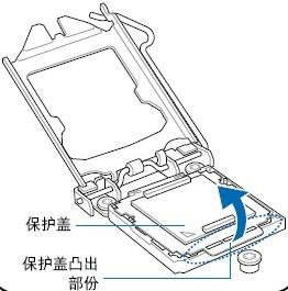
36 CVN B365M GAMING PRO V Safety Instructions To reduce the risk of fire, electric shock, and injury, always follow basic safety precautions. Remember to remove power from your computer by disconnecting the AC main source before removing or installing any equipment from/to the computer chassis. Installing the CPU The motherboard shipped in the box does not contain a CPU or memory. You need to purchase a CPU, a CPU fan assembly, and memory to complete this installation. Be very careful when handling the CPU. Make sure not to bend or break any pins on the back. Hold the processor only by the edges and do not touch the bottom of the processor. Use the following procedure to install the CPU onto the motherboard. 1. Unhook the socket lever by pushing down and away from the socket. 2. Lift the load plate. There is a protective socket cover on the load plate to protect the socket when there is no CPU installed. 3. Remove the protective socket cover from the load plate. 4. Remove the processor from its protective cover, making sure you hold it only by the edges. It is a good idea to save the cover so that whenever you remove the CPU, you have a safe place to store it. 5. Align the notches in the processor with the notches on the socket. 6. Lower the processor straight down into the socket with out tilting or sliding it into the socket Make sure the CPU is fully seated and level in the socket. 7. Close the load plate over the CPU and press down while you close and engage the socket lever. 8. There are many different fan types that can be used with this motherboard. Follow the instruction that came with you fan assembly. Be sure that the fan orientation is correct for your chassis type and your fan assembly. 30


37 The CPU fits in only one correct orientation. DO NOT force the CPU into the socket to prevent bending the connectors on the socket and damaging the CPU! Installing Memory DIMMs Your new motherboard has 4 slots for DDR4 memory. They support dual channel DDR4 memory technology. There must be at least one memory bank populated to ensure normal operation. Use the following the recommendations for installing memory. One DIMM: Install into DIMM1. You can install the DIMM into any slot, however, slot 1 is preferred. 2 DIMMs: Install into DIMM1&DIMM3 slot, or DIMM2&DIMM4 slot, to build dual channel. 31

38 CVN B365M GAMING PRO V20 3 DIMMs: don t install 3 DIMMs,may cause fault. 4 DIMMs: Install into DIMM1 DIMM2 DIMM3 DIMM4 slot. Use the following procedure to install memory DIMMs into the slots on the motherboard. Note that there is only one gap near the center of the DIMM slot. This slot matches the slot on the memory DIMM to ensure the component is installed properly. Unlock a DIMM slot by pressing the module clips outward. Align the memory module to the DIMM slot, and insert the module vertically into the DIMM slot. The plastic clips at both sides of the DIMM slot automatically lock the DIMM into the connector. Installing the Motherboard The sequence of installing the motherboard into the chassis depends on the chassis you are using and if you are replacing an existing motherboard or working with an empty chassis. Determine if it would be easier to make all the connections prior to this step or to secure the motherboard and then make all the connections. Use the following procedure to install the I/O shield and secure the motherboard into the chassis. Be sure that the CPU fan assembly has enough clearance for the chassis covers to lock into place and for the expansion cards. Also make sure the CPU Fan assembly is aligned with the vents on the covers. 32
39 Installing the I/O Shield The motherboard kit comes with an I/O shield that is used to block radio frequency transmissions, protects internal components from dust and foreign objects, and promotes correct airflow within the chassis. Before installing the motherboard, install the I/O shield from the inside of the chassis. Press the I/O shield into place and make sure it fits securely. If the I/O shield does not fit into the chassis, you would need to obtain the proper size from the chassis supplier. Securing the Motherboard into the Chassis Most computer chassis have a base with mounting studs or spacers to allow the mother board to be secured to the chassis and help to prevent short circuits. If there are studs that do not align with a mounting hole on the motherboard, it is recommended that you remove that stud to prevent the possibilityof a short circuit. 1. Carefully place the motherboard onto the studs/spacers located inside the chassis. 2. Align the mounting holes with the studs/spacers. 3. Align the connectors to the I/O shield. 4. Ensure that the fan assembly is aligned with the chassis vents according to the fan assembly instruction. 5. Secure the motherboard with a minimum of eight-to-ten screws Connecting header and Setting Switches This section takes you through all the connections and switch settings necessary on the motherboard. This will include: Power Connections 24-pin ATX power 8-pin ATX 12V power Internal Headers Front panel USB Headers Audio Serial ATA III Chassis Fans Rear panel USB 2.0 Adapter 33
40 CVN B365M GAMING PRO V20 Expansion slots ATX power connectors (24-pin ATXPWR, 8-pin ATX12V) These connectors are for an ATX power supply. The plugs from the power supply are designed to fit these connectors in only one orientation. Find the proper orientation and push down firmly until the connectors completely fit. Serial ATA 3.0 6Gb/s connectors (7-pin) These connectors connect to Serial ATA 3.0 6Gb/s hard disk drives and optical drives via Serial ATA 3.0 6Gb/s signal cables. 34
41 USB3.1 Gen1 connector This connector is for USB3.1 Gen1 devices. USB 2.0 connectors These connectors are for USB 2.0 ports. Connect the USB module cable to any of these connectors, then install the module to a slot opening at the back of the system chassis. These USB connectors comply with the USB 2.0 specification that supports up to 480Mbps connection speed. 35


42 CVN B365M GAMING PRO V20 Front panel audio connector This connector is for a chassis-mounted front panel audio I/O module that supports either High Definition Audio or AC`97 audio standard. Connect one end of the front panel audio I/O module cable to this connector. System panel connector This connector supports several chassis-mounted functions. System power LED (2-pin PLED) This 2-pin connector is for the system power LED. Connect the chassis power LED cable to this connector. The system power LED lights up when you turn on the system power, and blinks when the system is in sleep mode. Hard disk drive activity LED (2-pin IDE_LED) This 2-pin connector is for the HDD Activity LED. Connect the HDD Activity LED cable to this connector. The IDE LED lights up or flashes when data is read from or written to the HDD. System warning speaker (4-pin SPEAKER) 36
 This 2-pin connector is for the system power button.")
43 This 4-pin connector is for the chassis-mounted system warning speaker. The speaker allows you to hear system beeps and warnings. ATX power button/soft-off button (2-pin PWRSW) This 2-pin connector is for the system power button. Reset button (2-pin RESET) This 2-pin connector is for the chassis-mounted reset button for system reboot without turning off the system power. CPU Chassis and Power fan connectors Connect the fan cables to the fan connectors on the motherboard, making sure that the black wire of each cable matches the ground pin of the connector. The PCI Express x1 slots that are designed to accommodate less bandwidth-intensive cards, such as a modem or LAN card. The PCI Express x4 slots support X4 channel specifications. The PCI Express x16 slot is reserved for a graphics or video card. The bandwidth of the x16 slot is up to 4GB/sec (8GB/sec concurrent). When installing a PCI Express x16 card, be sure the retention clip snaps and locks the card into place. If the card is not seated properly, it could cause a short across the pins. Secure the card s metal bracket to the chassis back panel with the screw used to hold the blank cover. PCI Express x1,pci Express x4 & PCI Express x16 slots 37
44 CVN B365M GAMING PRO V20 M.2 Slot PCI Express3.0 x16 Slot PCI Express3.0 x1 Slot PCI Express3.0 x4 Slot The motherboard has two M.2 slots, supports PCI-e X4 SSD and Intel Optane technology and NVME standard,supports 2242/2260/2280 specification SSD,the data transfer rate can be as high as 32Gb/s. Intel OPTANE technology is the latest non-volatile storage technology of Intel. It is a technology between high performance and low latency between traditional memory and solid state hard disk. When using Intel OPTANE technology, the M.2 slot uses Intel dedicated OPTANE SSD, and is equipped with the latest processor, installing WIN10 64bit system and RST driver. In BIOS setting, we also need to open the Intel OPTANE technology option. Please install M.2 SSD correctly in the slot following the following steps: 1. please use a screwdriver to remove the screws and studs in order, and then lock the stud first when the actual M.2 SSD is found to be suitable for the screw hole position. 2. insert the M.2 SSD into the slot in a inclined angle. 3. press M.2 SSD, then lock the screw. 38


45 SPDIF header:jspdif1 This SPDIF header is for SPDIF audio devices. COM header:jcom This COM header is for COM serial devices SPEAK header: SPEAK This SPEAK header is for Speaker serial devices. 39

46 CVN B365M GAMING PRO V20 ME header:jme Intel Management Engine Interface,it is Intel management engine driven, is a heat management driver launched by Intel for its desktop series chipset.when you start the machine, Using a jumper cap or a metal short JME header in seconds, the ME program will be brushed and written. Clear CMOS Jumper: JBAT There is a CMOS RAM on board that has a power supply from external battery to keep the system configuration data. With the CMOS RAM, the system can automatically boot OS every time it is turned on. If you want to clear the system configuration, use the CLR_CMOS Jumper to clear data. Clear CMOS PROCEDURE You can clear CMOS by shorting 1-2 pin. Before you clearing the CMOS, following next procedure: 1 Turn off the AC power supply and connect pins 1 and 2 together using the jumper cap. 2 Return the jumper setting to normal (pin 1 or 2) or Remove the jumper cap 3 Turn the AC power supply back on. 40

.")
47 WiFi/BT module slot:m.2_wifi The motherboard has one WiFi/BT module slot, which supports the 2230 specification. The motherboard provides two RGB fan headers. When installing, the direction marked by the arrow on the connecting line should be aligned with the first pin of the header (the pin marked "12V" on the PCB board). In the BIOS option, you can set the color of the fan lamp, please refer to the BIOS settings for details. RGB FAN header:rgb1,rgb2 1-2 clear CMOS Clear CMOS settings 1or2 normal 41
48 CVN B365M GAMING PRO V Back Panel IO Connector <The back panel IO connector of CVN B365M GAMING PRO V20> Parts PS/2 Mouse/ Keyboard Connector LAN Jack Lie-In(Blue) Line Out(Green) Side R/L(Gray) DVI HDMI USB Ports Use This connector is for a PS/2 mouse/keyboard. The standard RJ-45 jack is for connection to single Local Area Network (LAN). You can connect a network cable to it. Used for external CD player, tape player or other audio devices. This connector for speakers or headphones. Side surround speakers connector Onboard DVI port, connect to DVI Monitor Onboard HDMI port, connect to HDMI Monitor These connectors are for attaching USB devices such as keyboard, mouse, or other USB-compatible devices. 42
49 5-3 BIOS Setting This chapter introduces how to change the system settings through BIOS settings. Pleaserefertothischapterfordetails. The chapter contains the following: Main(System Information) Advanced(Advanced BIOS Features) Chipset(Chipset Settings) Security(Security Settings) Boot(Startup Settings) C.Oclock(OverClock Settings) Enter BIOS Main Menu BIOS (Basic Input and Output System) records hardware parameters of the system in the CMOS on the motherboard. Its major functions include conducting the Power-On Self-Test (POST) during system startup,saving system parameters and loading operating system, etc. When computer startup, and then enter the boot self test (POST) program, if there are any errors will be shown the following information: Press DEL to enter Setup (Press the <DEL> key to enter BIOS Setup) If the boot self test (POST) program information is disappeared before you respond,you can turn it off and then turn on,or press the Reset button on the chassis to restart your computer, can alsopress<ctrl>+<alt>+<delete>torestartthecomputer. Since the BIOS version of the motherboard is constantly upgrading, the BIOS description is only for reference. 43
50 CVN B365M GAMING PRO V20 BIOS Setup Program Function Keys < > Upward and downward move to select a setup menu < > To the left and right move to select a setup menu < Enter > Execute command or enter a menu < Esc > Exit a menu or return to the main menu from submenu < +/PU > Increase the value or change the selection < -/PD > Reduce the value or change the selection < F1 > Help topic(only the status display menu and select Settings menu are valid) < F7> Restore the previous CMOS settings < F9> Load Optimized Defaults < F10 > Save all the changes and exit the BIOS setup program The BIOS settings can be operated with the mouse Main Advanced Chipset Security Boot C.Oclock BIOS Information BIOS Vendor Core Version Compliancy Project Version Build Date and Time Access Level ME FW Version Total Memory System Language System Date System Time American Megatrends 5.12 UEFI 2.7;PI 1.6 KBL0E /25/ :00:47 Administrator MB English 03/07/ : 22: 49 Select Screen /Click:Select Item Enter/ Dbl Click: Select +/-: Change Opt F1: General Help F7: Previous Values F9: Optimized Defaults F10: Save & Exit ESC: Exit Version Copyright (c) 2019 American Megatrends,Inc After entering the setup program, the first screen is the main menu 44
51 Main menu The main menu shows the set item category provided by BIOS. You can use the direction key to select different items. The hint information for the selected project is displayed at the bottom of the screen. Submenu Ifyoufindapointertotherightinaregionontheleft(asshowninthefigure above), thismeans that this item is attached to the submenu. Select this item, press the return to enter this option submenu. Then you can use the control key to move directly in the submenu and change the set value. Go back to the main menu and press <Esc>. Thematic help The BIOS setup program provides a help screen. You can adjust the help screen from any menu by simply pressing the <F1> key. This help screen lists the corresponding keys and possible selection items. Press <Esc> to exit the help screen BIOS Main Menu Main(System Information) Using this menu to view BIOS information and set up BIOS language, time and date. Advanced(Advanced BIOS Features) Using this menu to set up the advanced features of the system. Chipset(Chipset Settings) Using this menu to set corresponding settings for the chipset performance. Security(Security Settings) Using this menu to set corresponding settings the BIOS password accordingly Boot(Startup Settings) Using this menu to set corresponding settings for the computer boot device. C.Oclock(OverClock Settings) This menu can be used to overclock and optimize the performance of the system. 45
52 CVN B365M GAMING PRO V Main(System Information) System Language Selects the default language used by the BIOS. Options: English, Chinese, etc. System Date Set the date, the date format is <week><month><date><year> Week:from Sun.to Sat.,defined by the BIOS, read-only Month:from Jan.to Dec. Date:from 1 to 31,can be modified with numeric keys Year:user set the year fields System Time Set the time,the time format is<hour><minute><second> Advanced(Advanced BIOS Features) Main Advanced Chipset Security Boot C.Oclock CPU Configuration SATA And RST Configuration Power Management Configuration ACPI Settings Super IO Configuration Hardware Monitor USB Configuration CSM Configuration Select Screen Up/Down:Choose Item Enter/ Click: Select +/-: Change Opt F1: General Help F7: Previous Values F9: Optimized Defaults F10: Save & Reset ESC: Exit Version Copyright (c) 2019AmericanMegatrends,Inc 46
53 CPU Configuration(CPU setup) Intel (VMX) Virtualization Technology Open or close the Intel virtualization technology. Intel virtualization allows you to perform multiple operating systems and applications in the separate data partition of the same platform. Options: Disabled, Enabled. Intel (R) Speed Shift Technology Set whether to open Intel (R) Speed Shift Technology. Options:Disabled,Enabled. Active Processor Cores Set the number of the core of the activation processor. C sataes Open or close the CPU C status function. Options: Disabled, Enabled. SATA And RST Configuration (SATA and RST function settings) SATA Controller (S) Open or close the SATA controller. Options: Enabled, Disabled. SATA Mode Selection Set the work mode of the SATA interface. Options: AHCI, IRAID/Optane. SATA Controller Speed Set the speed of the SATA controller. Options: Default, Gen1, Gen2, Gen3. SATA Port1-6 Display SATA1-6 Ports connection status. Power Management Configuration (power supply setting) EUP Function Set up whether to open the EUP energy saving function. Options: Disabled, Enabled. When the PS/2 mouse / keyboard wake-up wake up, this option is set to "Disabled". USB KB/MS Wakeup Function Set up USB Keyboard/Mouse wake-up. Options: Disabled, Enabled. 47
54 CVN B365M GAMING PRO V20 Wake By Lan Set up network wake-up. Options: Disabled, Enabled. Power On By PS/2 Keyboard Set the PS/2 keyboard to boot. Options: Disabled, AnyKey (any key), Password (password). Power On By PS/2 Mouse Set the PS/2 mouse to boot. Options: Disabled, Enabled. AC Power Loss Set off the power after the call, the state of the PC. Options: Power On (boot), Power Off (shutdown), Last State (state of last power failure). Wake system from S5 Set up the system wake-up. Options: Disabled, Fixed Time (timing), Dynamic Time (dynamic time). When the "Fixed Time" is selected, the setting of the specific wake-up time will be popped. In the format of hours / minutes / seconds. The reasonable scope of each project is: Hour/ (0-23), Minute/ (0-59), Second/ sec (0-59). Red LED Control Set the color of RGB fan lamp to red.options: Disabled, Enabled. Green LED Control Set the color of RGB fan lamp to green.options: Disabled, Enabled. Blue LED Control Set the color of RGB fan lamp to blue.options: Disabled, Enabled. ACPI Settings (advanced configuration of ACPI) Enable ACPI Auto Configuration Set the ACPI auto configuration. Options: Disabled, Enabled. Select "Enabled", then ACPI will open all the supported sleep patterns; select "Disabled", then the following option will be popped. Enable Hibernation Opening or closing the operating system's sleep function. This option is only valid for a part of the operating system. Options: Disabled, Enabled. 48
55 ACPI Sleep State Select the standby mode under OS. Options: Suspend Disabled, S3 (Suspend to RAM). Super IO Configuration (super IO settings) PS/2 Port Setting Set the IO interface PS2 run mode. Options: Auto (automatic), KeyBoard (PS2 keyboard), Mouse (PS2 mouse), Disabled. Serial Port Configuration Clicking on the "Serial Port Configuration" option, there will be the following two sub options: Serial Port Start and close the serial port controller. Options: Disabled, Enabled. Change Settings (change settings) Thisoption is used to change the serial port address. Hardware Monitor (hardware monitoring) CPU / SYS Temperature Display the temperature of the current "CPU/ system". CPU FAN/ SYS FAN Speed Show the speed of current "CPU FAN/ SYS FAN". CPU VOL/DIMM VOL The current CPU voltage / memory voltage is displayed. CPU Smart FAN Controller Open or close intelligent operation of the CPU FAN. Options: Disabled, Enabled. USB Configuration Legacy USB Support Open or close the traditional USB device function. The traditional USB is an old 1.1USB device, and both the USB keyboard and the mouse belong to the 49
56 CVN B365M GAMING PRO V20 traditional USB. When using the USB keyboard and mouse, this option needs to be set to "Enabled". Options: Enabled, Disabled, Auto. XHCI Hand-off This project is used to start an operating system that supports no "XHCI hand-off" functionality. Options: Disabled, Enabled. USB Mass Storage Driver Support Set USB to support large capacity memory. Options: Disabled, Enabled. Port 60/64 Emulation USB port 60/64 simulation settings. When this function is enabled, the USB keyboard can enter some special combination keys. Options: Disabled,Enabled. USB transfer time-out This option sets the longest time for a data transmission on the USB2.0 bus. If the transmission is not completed during this time, the error is given to the EFI. This setting only works on EFI, and has no effect on the USB driver under OS.Options:1Sec,5Sec,10Sec,20Sec. Device reset time-out This option sets the longest time needed to store device reset on the USB2.0 bus. During this time, EFI will check whether the storage device can accept instructions. If the timeout is over, the storage device is considered to be wrong. Options: 10 Sec, 20 Sec, 30 Sec, 40 Sec. Device power-up delay This option sets the power delay on the USB device and can be accessed later. Set to "Auto", the data is obtained from the device; set to "Manual", the userentersthetimebyitself Chipset(chipset settings) System Agent(SA) Configuration (North Bridge configuration) Internal Graphics Set up or close the board integrated graphics card. Options: Auto, Disabled, Enabled. 50
57 PEG Max Link Speed Set the Maximum Speed of PEG(dedicated graphics). Options:Auto,Gen1,Gen2,Gen3. GTT Size Set memory size. Options: 2MB, 4MB, 8MB. IGFX Memory Size Set the set display capacity. Options: 32M, 64M, 128M, 256M, 512M, 1024M. DVMT Total GFX Mem Set the total capacity of explicit memory sharing. Options: 128MB, 256MB, MAX. VT-d Set up or close the Intel VT-d technology. Using Intel VT-d technology, virtual machine can use direct I/O device allocation or I/O device sharing instead of traditional device simulation / extra device interface mode, which greatly improves the I/O performance of virtualization. Options: Disabled, Enabled. PCH Device Configuration (south bridge equipment configuration) HD Audio Controller Open or close a high fidelity audio controller. Options: Disabled, Enabled, AUTO. Onboard LAN Controller Open or close the board controller. Options: Disabled, Enabled. PXE Boot Rom Open or close the PXE boot ROM boot. Options: Disabled, UEFI, Legacy Security(security settings) Administrator Password This project is used to set the password of the system administrator. Please follow the following steps: 1. select the "Administrator Password" project and press the "Enter" key. 2., when the "Greate New Password" window appears, the password you want to set in the input can be in English, digits and symbols within six bytes, and the input is completed by pressing the "Enter" key. 51
58 CVN B365M GAMING PRO V20 3. when the "Enter" key is pressed, the "Confirm New Password" window will appear, and again the password is entered to confirm the correct password. If the "Invalid Password" prompt information is presented, a mistake is entered when the password is confirmed, and reoperation is required. 4. if you want to change the password of the system administrator, please run the password settings again according to the above program. 5.press the "F10" key to save and exit, password settings can be effective. User Password Status This option is used to set the common user password. Select the "User Password" project and press the "Enter" key, and the rest of the steps refer to the system administrator password to operate Boot(Startup Settings) Setup Prompt Timeout When setting up the screen, the screen prompts the waiting time (second), and the number of seconds is required. "65535" represents an indefinite wait. Bootup Numlock State Set up a small number keyboard status when starting, Options: On (open), Off (close). Full LOGO Display Set up or close full screen display LOGO function. Options: Disabled, Enabled. ME Write Protect Turn ME write protection on or off. Turn this option off before flashing BIOS.Options: Disabled, Enabled. Boot Option Priorities Boot device priority settings.if the user wants to install the operating system, please set "Boot Option #1" as your drive device (CD-ROM) or your U disk device (provided that your CD-ROM drive has an operating system or your U disk has an PE system), When setup is complete, press the "F10" key to save and exit. The system will boot from your drive or U disk. 52
59 5-3-8 C.Oclock(OverClock Settings) OverClocking Performance Menu CPU OverClock Memory Configuration Voltage Configuration Main Advanced Chipset Security Boot Version Copyright (c) 2019AmericanMegatrends,Inc C.Oclock Select Screen Up/Down:Choose Item Enter/ Click: Select +/-: Change Opt F1: General Help F7: Previous Values F9: Optimized Defaults F10: Save & Reset ESC: Exit CPU OverClocking (CPU OverClock Configuration) CPU Flex Ratio Override Open or close overclock frequency for the installed CPU. Options: Disabled, Enabled. Intel(R)SpeedStep(tm) Set to open or close the enhanced Intel energy saving technology. It is an intelligent frequency reduction technology introduced by Intel. It can automatically adjust the voltage and frequency of the processor according to the different workload of the system to reduce the power consumption and heat. When overclocking, this option needs to be set to "Disabled". Options: Disabled, Enabled. Turbo Mode Set whether to turn on Turbo Mode. Options:Disabled and Enabled. 53
60 CVN B365M GAMING PRO V20 Memory Configuration (memory settings) Memory Profile (memory parameter setting) Set the memory time sequence. The setting values are Default Profile (default configuration), Custom Profile (custom settings, select this option, memory overclocking), XMP Profile1.The following can be used as a reference for supermemory frequency: Memory Frequency Set the memory frequency. tcl This item controls the C A S delay, which determines the delay time (in the time period) that the SDRAM starts reading after the receiving instruction. trcd/ trp Set the number of memory clocks to control the S D R A M. tras This item controls the minimum value of the R A S for the number of S D R A M memory clocks. trfc This field is used to select the automatic refresh cycle time. trrd The delay time between columns and columns of different B a n k is selected. trtp Select the precharge time. Voltage Configuration (voltage settings) Memory Voltage Set the memory voltage.manual input, within the V range. 54
61 Copyright Notice The material in this document is the intellectual property of Colorful Technology and Development CO, LTD. We take every care in the preparation of this document, but no guarantee is given as to the correctness of its contents. Our products are under continual improvement and we reserve the right to make changes without notice. Disclaimer The products name we mentioned in this manual is only for identifying, all of the brands belong to other company. The registered trademarks of IBM, VGA and PS/2 belong to International Business Machines. The registered trademarks of Intel, Pentium, Pentium Ⅱ, Celeron, Pentium III and Pentium 4 belong to Intel. The registered trademark of Athlon belongs to Advanced Micro Devices, Inc. The registered trademarks of Microsoft, MS-DOS, Windows 95/98/NT, Windows2000/XP etc. belong to Microsoft. All of the trademarks in this manual have been registered. Trademarks All trademarks in this manual are properties of their respective owners. NVIDIA is registered trademark of NVIDIA Corporation. AMD is registered trademarks of AMD Corporation. Intel is registered trademarks of Intel Corporation. Windows is registered trademarks of Microsoft Corporation. Inc. AMI is registered trademark of American Megatrends
62 Award is a registered trademark of Phoenix Technologies Ltd. Realtek is registered trademark of Realtek Semiconductor Corporation. JMicron is registered trademark of JMicron Technology Corporation. ASMedia is registered trademark of ASMedia Technology Inc. Technical Support If a problem arises with your system and no solution can be obtained from the user s manual, please contact your place of purchase or local distributor. Or our engineer, send the follow information to us! Customer name Contacts Contact address Product SN Dealer phone Purchase date Contact phone Product model Dealer name Dealer address Website: Service hotline:
P4i45GL_GV-R50-CN.p65
 1 Main Advanced Security Power Boot Exit System Date System Time Floppy Drives IDE Devices BIOS Version Processor Type Processor Speed Cache Size Microcode Update Total Memory DDR1 DDR2 Dec 18 2003 Thu
Serial ATA ( Silicon Image SiI3114)...2 (1) SATA... 2 (2) B I O S S A T A... 3 (3) RAID BIOS RAID... 5 (4) S A T A... 8 (5) S A T A... 10
...2 (1) SATA... 2 (2) B I O S S A T A... 3 (3) RAID BIOS RAID... 5 (4) S A T A... 8 (5) S A T A... 10") Serial ATA ( Silicon Image SiI3114)...2 (1) SATA... 2 (2) B I O S S A T A... 3 (3) RAID BIOS RAID... 5 (4) S A T A... 8 (5) S A T A... 10 Ác Åé å Serial ATA ( Silicon Image SiI3114) S A T A (1) SATA (2)
Serial ATA ( Silicon Image SiI3114)...2 (1) SATA... 2 (2) B I O S S A T A... 3 (3) RAID BIOS RAID... 5 (4) S A T A... 8 (5) S A T A... 10 Ác Åé å Serial ATA ( Silicon Image SiI3114) S A T A (1) SATA (2)
P4V88+_BIOS_CN.p65
 1 Main H/W Monitor Boot Security Exit System Overview System Time System Date [ 17:00:09] [Wed 12/22/2004] BIOS Version : P4V88+ BIOS P1.00 Processor Type : Intel (R) Pentium (R) 4 CPU 2.40 GHz Processor
P4Dual-915GL_BIOS_CN.p65
 1 Main H/W Monitor Boot Security Exit System Overview System Time System Date Total Memory DIMM 1 DIMM 2 [ 14:00:09] [Wed 01/05/2005] BIOS Version : P4Dual-915GL BIOS P1.00 Processor Type : Intel (R) Pentium
P4VM800_BIOS_CN.p65
 1 Main H/W Monitor Boot Security Exit System Overview System Time System Date [ 17:00:09] [Fri 02/25/2005] BIOS Version : P4VM800 BIOS P1.00 Processor Type : Intel (R) Pentium (R) 4 CPU 2.40 GHz Processor
775i65PE_BIOS_CN.p65
 1 Main H/W Monitor Boot Security Exit System Overview System Time System Date [ 14:00:09] [Wed 10/20/2004] BIOS Version : 775i65PE BIOS P1.00 Processor Type : Intel (R) CPU 3.20 GHz Processor Speed : 3200
如 果 此 設 備 對 無 線 電 或 電 視 接 收 造 成 有 害 干 擾 ( 此 干 擾 可 由 開 關 設 備 來 做 確 認 ), 用 戶 可 嘗 試 用 以 下 一 種 或 多 種 方 法 來 消 除 這 個 干 擾 : 重 新 調 整 與 確 定 接 收 天 線 方 向 增 大 此 設
, 用 戶 可 嘗 試 用 以 下 一 種 或 多 種 方 法 來 消 除 這 個 干 擾 : 重 新 調 整 與 確 定 接 收 天 線 方 向 增 大 此 設") 版 權 前 言 本 出 版 物, 包 括 所 有 照 片 插 圖 與 軟 體 均 受 國 際 版 權 法 之 保 護, 所 有 權 利 均 被 保 留 此 說 明 書 和 其 中 所 包 含 的 任 何 材 料 都 不 可 以 在 沒 有 作 者 的 書 面 許 可 下 被 複 製 版 本 1.0 免 責 聲 明 製 造 商 不 對 說 明 書 內 容 作 任 何 陳 述 或 擔 保, 基 於 此
版 權 前 言 本 出 版 物, 包 括 所 有 照 片 插 圖 與 軟 體 均 受 國 際 版 權 法 之 保 護, 所 有 權 利 均 被 保 留 此 說 明 書 和 其 中 所 包 含 的 任 何 材 料 都 不 可 以 在 沒 有 作 者 的 書 面 許 可 下 被 複 製 版 本 1.0 免 責 聲 明 製 造 商 不 對 說 明 書 內 容 作 任 何 陳 述 或 擔 保, 基 於 此
Ác Åé å Serial ATA ( Sil3132) S A T A (1) SATA (2) BIOS SATA (3)* RAID BIOS RAID (4) SATA (5) SATA (a) S A T A ( S A T A R A I D ) (b) (c) Windows XP
 S A T A (1) SATA (2) BIOS SATA (3)* RAID BIOS RAID (4) SATA (5) SATA (a) S A T A ( S A T A R A I D ) (b) (c) Windows XP") Serial ATA ( Sil3132)...2 (1) SATA... 2 (2) B I O S S A T A... 3 (3) RAID BIOS RAID... 6 (4) S A T A... 10 (5) S A T A... 12 Ác Åé å Serial ATA ( Sil3132) S A T A (1) SATA (2) BIOS SATA (3)* RAID BIOS
Serial ATA ( Sil3132)...2 (1) SATA... 2 (2) B I O S S A T A... 3 (3) RAID BIOS RAID... 6 (4) S A T A... 10 (5) S A T A... 12 Ác Åé å Serial ATA ( Sil3132) S A T A (1) SATA (2) BIOS SATA (3)* RAID BIOS
CANVIO_AEROCAST_CS_EN.indd
 简 体 中 文...2 English...4 SC5151-A0 简 体 中 文 步 骤 2: 了 解 您 的 CANVIO AeroCast CANVIO AeroCast 无 线 移 动 硬 盘 快 速 入 门 指 南 欢 迎 并 感 谢 您 选 择 TOSHIBA 产 品 有 关 您 的 TOSHIBA 产 品 的 详 情, 请 参 阅 包 含 更 多 信 息 的 用 户 手 册 () 安
1.ai
 HDMI camera ARTRAY CO,. LTD Introduction Thank you for purchasing the ARTCAM HDMI camera series. This manual shows the direction how to use the viewer software. Please refer other instructions or contact
P3B-F Pentium III/II/Celeron TM
 P3B-F Pentium III/II/Celeron TM 1999 2 3 4 5 6 7 8 9 10 11 12 1 2 3 4 5 22 21 20 19 18 17 16 15 14 13 12 11 10 9 8 7 6 13 R PS2 KBMS USB COM1 COM2 JTPWR ATXPWR PWR_FAN CPU_FAN Row 0 1 2 3 4 5 6 7 DSW JP20
T
 T10452 2015 5 Copyright ASUSTeK Computer Inc. All rights reserved. http://support.asus.com 0800-093-456 1 2 2 筆記型電腦使用手冊 使用手冊... 7 手冊... 8... 8... 8... 9 使用... 9...10...10 筆記型電腦...12...12...16...18...20...22
Serial ATA ( Nvidia nforce430)...2 (1) SATA... 2 (2) B I O S S A T A... 3 (3) RAID BIOS RAID... 6 (4) S A T A... 9 (5) S A T A (6) Microsoft Win
...2 (1) SATA... 2 (2) B I O S S A T A... 3 (3) RAID BIOS RAID... 6 (4) S A T A... 9 (5) S A T A (6) Microsoft Win") Serial ATA ( Nvidia nforce430)...2 (1) SATA... 2 (2) B I O S S A T A... 3 (3) RAID BIOS RAID... 6 (4) S A T A... 9 (5) S A T A... 11 (6) Microsoft Windows 2000... 14 Ác Åé å Serial ATA ( Nvidia nforce430)
Serial ATA ( Nvidia nforce430)...2 (1) SATA... 2 (2) B I O S S A T A... 3 (3) RAID BIOS RAID... 6 (4) S A T A... 9 (5) S A T A... 11 (6) Microsoft Windows 2000... 14 Ác Åé å Serial ATA ( Nvidia nforce430)
Product Type Batteries (only) Circuit Breatkers & Load Protection Connection Devices Contactors Ethernet Switches, Stratix Switches I/O Modules; PLC N
 Circuit Breatkers & Load Protection Connection Devices Contactors Ethernet Switches, Stratix Switches I/O Modules; PLC N") 1201 South Second Street Milwaukee, Wisconsin U.S.A. 53204 Tel 414-382-2000 1 July 2016 RE: China Restriction of Hazardous Substances (RoHS) Dear Customer, Rockwell Automation is committed to demonstrating
1201 South Second Street Milwaukee, Wisconsin U.S.A. 53204 Tel 414-382-2000 1 July 2016 RE: China Restriction of Hazardous Substances (RoHS) Dear Customer, Rockwell Automation is committed to demonstrating
P3V4X JumperFree TM
 P3V4X JumperFree TM 1999 2 3 4 5 6 7 8 9 10 11 12 1 2 3 4 5 6 7 8 9 10 11 12 13 14 15 16 17 18 19 20 21 22 1 2 3 4 5 6 22 21 20 19 18 17 16 15 14 13 12 11 10 9 8 7 13 19.3cm (7.6in) COM1 COM2 PS2KBMS JTPWR
K7M SLOT 1
 K7M SLOT 1 1999 2 3 4 5 6 7 8 9 10 11 12 1 2 3 4 5 6 7 8 9 10 11 12 13 14 15 16 17 18 19 20 21 22 23 1 2 3 4 5 6 23 22 21 20 19 18 17 16 15 14 13 12 11 10 9 8 7 13 USB PS/2 COM1 COM2 CPU Core Voltage Setting
Product Type Batteries (only) Circuit Breakers & Load Protection Connection Devices Contactors Ethernet Switches, Stratix Switches I/O Modules; PLC Ne
 Circuit Breakers & Load Protection Connection Devices Contactors Ethernet Switches, Stratix Switches I/O Modules; PLC Ne") 1201 South Second Street Milwaukee, Wisconsin U.S.A. 53204 Tel 414-382-2000 1 July 2016 RE: China Restriction of Hazardous Substances (RoHS) Dear Customer, Rockwell Automation is committed to demonstrating
1201 South Second Street Milwaukee, Wisconsin U.S.A. 53204 Tel 414-382-2000 1 July 2016 RE: China Restriction of Hazardous Substances (RoHS) Dear Customer, Rockwell Automation is committed to demonstrating
K7VT2_QIG_v3
 ............ 1 2 3 4 5 [R] : Enter Raid setup utility 6 Press[A]keytocreateRAID RAID Type: JBOD RAID 0 RAID 1: 2 7 RAID 0 Auto Create Manual Create: 2 RAID 0 Block Size: 16K 32K
TX-NR3030_BAS_Cs_ indd
 TX-NR3030 http://www.onkyo.com/manual/txnr3030/adv/cs.html Cs 1 2 3 Speaker Cable 2 HDMI OUT HDMI IN HDMI OUT HDMI OUT HDMI OUT HDMI OUT 1 DIGITAL OPTICAL OUT AUDIO OUT TV 3 1 5 4 6 1 2 3 3 2 2 4 3 2 5
T
 T10362 2015 5 Copyright ASUSTeK Computer Inc. All rights reserved. http://support.asus.com 0800-093-456 1 2 2 筆記型電腦使用手冊 使用手冊... 7 手冊... 8... 8... 8... 9 使用... 9...10...10 Energy Star...11 筆記型電腦...14...14...18...20...22...24
RAID RAID 0 RAID 1 RAID 5 RAID * ( -1)* ( /2)* No Yes Yes Yes A. B. BIOS SATA C. RAID BIOS RAID ( ) D. SATA RAID/AHCI ( ) SATA M.2 SSD ( )
* ( /2)* No Yes Yes Yes A. B. BIOS SATA C. RAID BIOS RAID ( ) D. SATA RAID/AHCI ( ) SATA M.2 SSD ( )") RAID RAID 0 RAID 1 RAID 5 RAID 10 2 2 3 4 * (-1)* (/2)* No Yes Yes Yes A. B. BIOS SATA C. RAID BIOS RAID ( ) D. SATA RAID/AHCI ( ) SATA M.2 SSD ( ) ( ) ( ) Windows USB 1 SATA A. SATASATAIntel SATA (SATA3
RAID RAID 0 RAID 1 RAID 5 RAID 10 2 2 3 4 * (-1)* (/2)* No Yes Yes Yes A. B. BIOS SATA C. RAID BIOS RAID ( ) D. SATA RAID/AHCI ( ) SATA M.2 SSD ( ) ( ) ( ) Windows USB 1 SATA A. SATASATAIntel SATA (SATA3
P3C2000 JumperFree TM Camino
 P3C2000 JumperFree TM Camino 1999 2 3 4 5 6 7 8 9 10 11 12 1 2 3 4 5 6 7 8 9 10 11 12 13 14 15 16 17 18 19 20 21 22 23 24 25 26 1 2 3 4 5 6 7 26 25 24 23 22 21 20 19 18 17 16 15 14 13 12 11 10 9 8 13 USB
典型自编教材
 河 南 科 技 大 学 计 算 机 实 验 教 学 中 心 1. 计 算 机 文 化 基 础 实 验 指 导 书 2. 数 据 结 构 实 验 指 导 书 3. 操 作 系 统 实 验 指 导 书 4. 面 向 对 象 程 序 设 计 实 验 指 导 书 5. 数 据 库 原 理 实 验 指 导 书 6. 编 译 原 理 实 验 指 导 书 7. JAVA 程 序 设 计 实 验 指 导 书 8.
GA-8IG P4 533 Pentium Rev MC-8IG-1201
 GA-8IG P4 533 Pentium Rev. 20 2MC-8IG-20 ... 3... 3... 4... 4 GA-8IG Layout... 6... 7 (CPU... 8 -... 8-2... 9 2... 0 3... 2 4:... 3 4- I/O... 3 4-2... 5 4-3... 2 GA-8IG - 2 - GA-8IG GA-8IG x / x x. 2.
Logitech Wireless Combo MK45 English
 Logitech Wireless Combo MK45 Setup Guide Logitech Wireless Combo MK45 English................................................................................... 7..........................................
Ác Åé å Serial ATA ( nvidia nforce4 SLI) S A T A (1) SATA (2) BIOS SATA (3)* RAID BIOS RAID (4) SATA (5) SATA (a) S A T A ( S A T A R A I D ) (b) (c)
 S A T A (1) SATA (2) BIOS SATA (3)* RAID BIOS RAID (4) SATA (5) SATA (a) S A T A ( S A T A R A I D ) (b) (c)") Serial ATA ( nvidia nforce4 SLI)...2 (1) SATA... 2 (2) B I O S S A T A... 3 (3) RAID BIOS RAID... 6 (4) S A T A... 9 (5) S A T A... 11 (6) Microsoft Windows 2000... 14 Ác Åé å Serial ATA ( nvidia nforce4
Serial ATA ( nvidia nforce4 SLI)...2 (1) SATA... 2 (2) B I O S S A T A... 3 (3) RAID BIOS RAID... 6 (4) S A T A... 9 (5) S A T A... 11 (6) Microsoft Windows 2000... 14 Ác Åé å Serial ATA ( nvidia nforce4
Serial ATA ( nvidia nforce4 Ultra/SLI)...2 (1) SATA... 2 (2) B I O S S A T A... 3 (3) RAID BIOS RAID... 6 (4) S A T A... 9 (5) S A T A (6) Micro
...2 (1) SATA... 2 (2) B I O S S A T A... 3 (3) RAID BIOS RAID... 6 (4) S A T A... 9 (5) S A T A (6) Micro") Serial ATA ( nvidia nforce4 Ultra/SLI)...2 (1) SATA... 2 (2) B I O S S A T A... 3 (3) RAID BIOS RAID... 6 (4) S A T A... 9 (5) S A T A... 11 (6) Microsoft Windows 2000... 14 Ác Åé å Serial ATA ( nvidia
Serial ATA ( nvidia nforce4 Ultra/SLI)...2 (1) SATA... 2 (2) B I O S S A T A... 3 (3) RAID BIOS RAID... 6 (4) S A T A... 9 (5) S A T A... 11 (6) Microsoft Windows 2000... 14 Ác Åé å Serial ATA ( nvidia
AL-M200 Series
 NPD4754-00 TC ( ) Windows 7 1. [Start ( )] [Control Panel ()] [Network and Internet ( )] 2. [Network and Sharing Center ( )] 3. [Change adapter settings ( )] 4. 3 Windows XP 1. [Start ( )] [Control Panel
IT (1) IDE... 2 (2) BIOS IDE RAID... 3 (3) RAID BIOS RAID... 5 (4) R A I D (5) ID E RA ID... 15
 IDE... 2 (2) BIOS IDE RAID... 3 (3) RAID BIOS RAID... 5 (4) R A I D (5) ID E RA ID... 15") IT8212...2 (1) IDE... 2 (2) BIOS IDE RAID... 3 (3) RAID BIOS RAID... 5 (4) R A I D... 13 (5) ID E RA ID... 15 Ác Åé å IT8212 (1) IDE (2) BIOS IDE RAID (3) RAID BIOS RAID (4) RAID (5) RAID (a) ( )IDE (
IT8212...2 (1) IDE... 2 (2) BIOS IDE RAID... 3 (3) RAID BIOS RAID... 5 (4) R A I D... 13 (5) ID E RA ID... 15 Ác Åé å IT8212 (1) IDE (2) BIOS IDE RAID (3) RAID BIOS RAID (4) RAID (5) RAID (a) ( )IDE (
+01-10_M5A_C1955.p65
 Notebook PC User s Manual C1955 1.01 2005 4 2 50 70 3 (0 30 ) (50 122 ) 4 pre-load Fn+F7 5 ...2...3...6 1-1...12...12...13...14...15...16...17 1-2...18 1-3...20...20...21...21...21...21...22...22...22...22...23...23
Guide to Install SATA Hard Disks
 SATA RAID 1. SATA. 2 1.1 SATA. 2 1.2 SATA 2 2. RAID (RAID 0 / RAID 1 / JBOD).. 4 2.1 RAID. 4 2.2 RAID 5 2.3 RAID 0 6 2.4 RAID 1.. 10 2.5 JBOD.. 16 3. Windows 2000 / Windows XP 20 1. SATA 1.1 SATA Serial
01CP-WX3030WNetc_CO_ENG.indd
 Data Video Projector User s Manual (Concise) ModelS: 8928A/8930A/8931WA/ 8933W Information in this Guide may change due to product improvements. To obtain the latest manuals, literature, and software please
K301Q-D VRT中英文说明书141009
 THE INSTALLING INSTRUCTION FOR CONCEALED TANK Important instuction:.. Please confirm the structure and shape before installing the toilet bowl. Meanwhile measure the exact size H between outfall and infall
Product Specification Chip Intel DSL6540 Thunderbolt 3 Controller Connectors 2 x Thunderbolt 3 ports (Thunderbolt 3 Port 1/Thunderbolt 3 Port 2), supp
, supp") GC-ALPINE RIDGE Installation Guide/ 12WE6-ALPINER-10AR Product Specification Chip Intel DSL6540 Thunderbolt 3 Controller Connectors 2 x Thunderbolt 3 ports (Thunderbolt 3 Port 1/Thunderbolt 3 Port 2),
GC-ALPINE RIDGE Installation Guide/ 12WE6-ALPINER-10AR Product Specification Chip Intel DSL6540 Thunderbolt 3 Controller Connectors 2 x Thunderbolt 3 ports (Thunderbolt 3 Port 1/Thunderbolt 3 Port 2),
HistoCore ArcadiaH Instruction for Use, V1.8, RevK
 HistoCore Arcadia H 14 0393 88102 - K 1.8 K - 10.2018 HistoCore Arcadia H 258 15301 021-58994990 258 15301 258 15301 021-58994990 20010623 20150115 20150115 () 127 3 C 021-80316300 021-80316298 () ( )
RAID RAID 0 RAID 1 RAID 5 RAID * (-1)* (/ 2)* No Yes Yes Yes SATA A. B. BIOS SATA C. RAID BIOS RAID ( ) D. RAID/AHCI ( ) S ATA S S D ( ) (
* (/ 2)* No Yes Yes Yes SATA A. B. BIOS SATA C. RAID BIOS RAID ( ) D. RAID/AHCI ( ) S ATA S S D ( ) (") SATA... 2 RAID/AHCI... 16 Intel Optane... 19 Intel Virtual RAID on CPU (Intel VROC)... 21 RAID RAID 0 RAID 1 RAID 5 RAID 10 2 2 3 4 * (-1)* (/ 2)* No Yes Yes Yes SATA A. B. BIOS SATA C. RAID BIOS RAID
SATA... 2 RAID/AHCI... 16 Intel Optane... 19 Intel Virtual RAID on CPU (Intel VROC)... 21 RAID RAID 0 RAID 1 RAID 5 RAID 10 2 2 3 4 * (-1)* (/ 2)* No Yes Yes Yes SATA A. B. BIOS SATA C. RAID BIOS RAID
Microsoft Word - template.doc
 HGC efax Service User Guide I. Getting Started Page 1 II. Fax Forward Page 2 4 III. Web Viewing Page 5 7 IV. General Management Page 8 12 V. Help Desk Page 13 VI. Logout Page 13 Page 0 I. Getting Started
T1028_Manual_KO_V3 0.pdf
 2009 : 2009/09 PC Microsoft, MS-DOS, Windows, Windows Sound System Microsoft Corporation Intel, Atom Intel Corporation Sound Blaster, Sound Blaster ProCreative Technology I AC AC AC AC AC - 115 V/60 Hz
AL-MX200 Series
 PostScript Level3 Compatible NPD4760-00 TC Seiko Epson Corporation Seiko Epson Corporation ( ) Seiko Epson Corporation Seiko Epson Corporation Epson Seiko Epson Corporation Apple Bonjour ColorSync Macintosh
Product Specification Chip Connectors Interface Data Transfer Rate Intel DSL5520 Thunderbolt 2 Controller 2 x Thunderbolt 2 ports (TBT 1/TBT 2), suppo
, suppo") GC-Thunderbolt 2 Installation Guide/ 12WE6-TH2-10AR Product Specification Chip Connectors Interface Data Transfer Rate Intel DSL5520 Thunderbolt 2 Controller 2 x Thunderbolt 2 ports (TBT 1/TBT 2), supporting
GC-Thunderbolt 2 Installation Guide/ 12WE6-TH2-10AR Product Specification Chip Connectors Interface Data Transfer Rate Intel DSL5520 Thunderbolt 2 Controller 2 x Thunderbolt 2 ports (TBT 1/TBT 2), supporting
ebook140-9
 9 VPN VPN Novell BorderManager Windows NT PPTP V P N L A V P N V N P I n t e r n e t V P N 9.1 V P N Windows 98 Windows PPTP VPN Novell BorderManager T M I P s e c Wi n d o w s I n t e r n e t I S P I
Windows 2000 Server for T100
 2 1 Windows 95/98 Windows 2000 3.5 Windows NT Server 4.0 2 Windows DOS 3.5 T200 2002 RAID RAID RAID 5.1 Windows 2000 Server T200 2002 Windows 2000 Server Windows 2000 Server Windows 2000 Server 3.5 for
热设计网
 例 例 Agenda Popular Simulation software in PC industry * CFD software -- Flotherm * Advantage of Flotherm Flotherm apply to Cooler design * How to build up the model * Optimal parameter in cooler design
Windows XP
 Windows XP What is Windows XP Windows is an Operating System An Operating System is the program that controls the hardware of your computer, and gives you an interface that allows you and other programs
Serial ATA ( Silicon Image SiI3512)...2 (1) SATA... 2 (2) B I O S S A T A... 3 (3) RAID BIOS RAID... 5 (4) S A T A... 8 (5) S A T A... 10
...2 (1) SATA... 2 (2) B I O S S A T A... 3 (3) RAID BIOS RAID... 5 (4) S A T A... 8 (5) S A T A... 10") Serial ATA ( Silicon Image SiI3512)...2 (1) SATA... 2 (2) B I O S S A T A... 3 (3) RAID BIOS RAID... 5 (4) S A T A... 8 (5) S A T A... 10 Ác Åé å Serial ATA ( Silicon Image SiI3512) S A T A (1) SATA (2)
Serial ATA ( Silicon Image SiI3512)...2 (1) SATA... 2 (2) B I O S S A T A... 3 (3) RAID BIOS RAID... 5 (4) S A T A... 8 (5) S A T A... 10 Ác Åé å Serial ATA ( Silicon Image SiI3512) S A T A (1) SATA (2)
BC04 Module_antenna__ doc
 http://www.infobluetooth.com TEL:+86-23-68798999 Fax: +86-23-68889515 Page 1 of 10 http://www.infobluetooth.com TEL:+86-23-68798999 Fax: +86-23-68889515 Page 2 of 10 http://www.infobluetooth.com TEL:+86-23-68798999
solutions guide
 solutions guide Tridium 01 Table of Contents Tridium... 1 Frameworks... 4 Niagara AX Framework... 5 Sedona Framework... 6.... 7 NPM... 8 Sedona Chip... 9 AX Supervisor... 10 AX SoftJACE...11...12. JACE
c-AR64SH-102
 Chapter 2 GIGA-BYTE TECHNOLOGY CO, LTD GBT ( ) GBT GBT, GBT 2002 3 15 1 1 11 3 12 3 2 21 4 22 5 23 6 3 31 Win 98/ 98SE, WinME Win XP 8 311 8 312 Direct X 9 313 11 314 14 315 14 316 18 32 Windows NT 40
Important Notice SUNPLUS TECHNOLOGY CO. reserves the right to change this documentation without prior notice. Information provided by SUNPLUS TECHNOLO
 Car DVD New GUI IR Flow User Manual V0.1 Jan 25, 2008 19, Innovation First Road Science Park Hsin-Chu Taiwan 300 R.O.C. Tel: 886-3-578-6005 Fax: 886-3-578-4418 Web: www.sunplus.com Important Notice SUNPLUS
Panaboard Overlayer help
 Panaboard Overlayer Image Capture Software for Electronic Whiteboard (Panaboard) ... 3... 5... 6... 13...14 Panaboard Overlayer 1. 2. 3. 4. 4-1. 4-2. [ / ] ( ) 4-3. 5. 6. 6-1. 6-2. [ / ] ( ) 7. Panaboard
IP505SM_manual_cn.doc
 IP505SM 1 Introduction 1...4...4...4...5 LAN...5...5...6...6...7 LED...7...7 2...9...9...9 3...11...11...12...12...12...14...18 LAN...19 DHCP...20...21 4 PC...22...22 Windows...22 TCP/IP -...22 TCP/IP
8idml_20_1_q
 Chapter 2 GIGA-BYTE TECHNOLOGY CO, LTD GBT ( ) GBT GBT, GBT 2002 3 15 1 1 11 3 12 AP64D(-H) 3 2 21 4 22 5 23 6 3 31 Win 98/98SE, WinME Win XP 8 311 8 312 Direct X 9 313 11 314 14 315 14 316 18 32 Windows
untitled
 Copyright 2008 2009/09 Microsoft MS-DOS Windows Windows Sound System Microsoft Corporation Intel Centrino Centrino Duo Pentium M Banias Calexico Intel Corporation Sound Blaster Sound Blaster Pro Creative
PTS7_Manual.PDF
 User Manual Soliton Technologies CO., LTD www.soliton.com.tw - PCI V2.2. - PCI 32-bit / 33MHz * 2 - Zero Skew CLK Signal Generator. - (each Slot). -. - PCI. - Hot-Swap - DOS, Windows 98/2000/XP, Linux
Olav Lundström MicroSCADA Pro Marketing & Sales 2005 ABB - 1-1MRS755673
 Olav Lundström MicroSCADA Pro Marketing & Sales 2005 ABB - 1 - Contents MicroSCADA Pro Portal Marketing and sales Ordering MicroSCADA Pro Partners Club 2005 ABB - 2 - MicroSCADA Pro - Portal Imagine that
Chapter 2
 2 (Setup) ETAP PowerStation ETAP ETAP PowerStation PowerStation PowerPlot ODBC SQL Server Oracle SQL Server Oracle Windows SQL Server Oracle PowerStation PowerStation PowerStation PowerStation ETAP PowerStation
第4章 系统设置
 POST 4.1 POST BIOS POST POST POST POST LOGO LOGO POST BIOS POST POST SCSI SCSI BIOS RAID POST RAID RAID RAID BIOS Operating System not Found BIOS T200 2002 BIOS 4.2 BIOS BIOS
AP128DG-H AP128DG-H 3 13 ATiRADEON TM Win 98/98SE, WinME Win XP Direct X
 Chapter 2 GIGA-BYTE TECHNOLOGY CO, LTD ( GBT ) GBT GBT, GBT 2002 4 12 1 AP128DG-H 1 11 3 12 AP128DG-H 3 13 ATiRADEON TM 8500 4 2 21 5 22 6 23 7 3 31 Win 98/98SE, WinME Win XP 9 311 9 312 Direct X 10 313
Dell Vostro 14–3459 用户手册
 Dell Vostro 14 3459 用 户 手 册 管 制 型 号 : P65G 管 制 类 型 : P65G003 注 小 心 和 警 告 注 : 注 表 示 可 以 帮 助 您 更 好 地 使 用 计 算 机 的 重 要 信 息 小 心 : 小 心 表 示 可 能 会 损 坏 硬 件 或 导 致 数 据 丢 失, 并 如 何 避 免 此 类 问 题 警 告 : 警 告 表 示 可 能 会 造
Microsoft Word - 战斧C.B150A 魔音版 V20.doc
 战斧 C.B150A 魔音版 V20 网驰 B150A-PRO V20 战斧 C.B150A 魔音版 V20/ 网驰 B150A-PRO V20 目录 第一章简介... 1 1-1 主板特色... 1 1-2 主板规格... 1 1-3 主板布局图... 3 第二章硬件安装... 5 2-1 基本硬件安装... 5 2-2 跳线设置... 7 2-3 连接器和引脚连接头... 9 2-4 背板接口介绍...
TPM BIOS Infineon TPM Smart TPM Infineon TPM Smart TPM TPM Smart TPM TPM Advanced Mode...8
 Smart TPM Rev. 1001 Smart TPM Ultra TPM Smart TPM TPM...3 1. BIOS... 3 2. Infineon TPM Smart TPM... 4 2.1. Infineon TPM...4 2.2. Smart TPM...4 3. TPM... 5 3.1. Smart TPM TPM...5 3.2. Advanced Mode...8
Microsoft Word - 战斧C.B150M-ET魔音版V20.doc
 战斧 C.B150M-ET 魔音版 V20 战斧 C.B150M-ET 魔音版 V20 目录 第一章简介... 1 1-1 主板特色... 1 1-2 主板规格... 1 1-3 主板布局图... 3 第二章硬件安装... 4 2-1 基本硬件安装... 4 2-2 跳线设置... 7 2-3 连接器和引脚连接头... 8 2-4 背板接口介绍... 13 第三章驱动程序安装说明... 14 第四章
入學考試網上報名指南
 入 學 考 試 網 上 報 名 指 南 On-line Application Guide for Admission Examination 16/01/2015 University of Macau Table of Contents Table of Contents... 1 A. 新 申 請 網 上 登 記 帳 戶 /Register for New Account... 2 B. 填
LH_Series_Rev2014.pdf
 REMINDERS Product information in this catalog is as of October 2013. All of the contents specified herein are subject to change without notice due to technical improvements, etc. Therefore, please check
<4D6963726F736F667420576F7264202D2032303130C4EAC0EDB9A4C0E04142BCB6D4C4B6C1C5D0B6CFC0FDCCE2BEABD1A15F325F2E646F63>
 2010 年 理 工 类 AB 级 阅 读 判 断 例 题 精 选 (2) Computer mouse How does the mouse work? We have to start at the bottom, so think upside down for now. It all starts with mouse ball. As the mouse ball in the bottom
5in1_eDVR_Manual_Chinese.cdr
 02 English User Manual 29 User Manual Contents 2 5 6 7 8 9 10 11 12 14 17 18 19 20 21 22 23 24 25 26 27 Quick start Controls Accessories Minimum System Requirements Battery Charge Power On/Off LCM Indicator
WFC40810
 9000086873 (PD 85 05 10) Operating and Installation Instructions Please read this specification carefully before you use the product. Any failure and losses caused by ignoring the above mentioned items
Desktop Management Guide
 Ĵ* 商 用 台 式 机 文 档 部 件 号 312947-AA1 2003 詤 3 本 指 南 介 绍 了 预 装 在 某 些 机 型 上 的 安 全 保 护 功 能 和 智 能 管 理 功 能 的 定 义 及 使 用 说 明 2002 Hewlett-Packard Company 2002 Hewlett-Packard Development Company, L.P. HP Hewlett
GIGA-BYTE TECHNOLOGY CO., LTD. ("GBT") GBT GBT GBT
 GBT GBT GBT") GIGA-BYTE TECHNOLOGY CO., LTD. ("GBT") GBT GBT GBT 2003 11 6-1 - 1....3 1.1.... 3 1.2.... 3 2....4 2.1.... 4 2.2.... 5 2.3.... 6 3....8 3.1. Win XP... 8 3.1.1....8 3.1.2. DirectX...9 3.1.3.... 11 3.1.4....15
GIGA-BYTE TECHNOLOGY CO., LTD. ("GBT") GBT GBT GBT 2003 11 6-1 - 1....3 1.1.... 3 1.2.... 3 2....4 2.1.... 4 2.2.... 5 2.3.... 6 3....8 3.1. Win XP... 8 3.1.1....8 3.1.2. DirectX...9 3.1.3.... 11 3.1.4....15
CHN_p000A_Cover.ai
 NextoDI Co., Ltd. www.nextodi.com 列表........................................................................ 1 3 4 4 6 7 8 9 10 12 14 16 20 01 02 03 04 1 2 3 5 6 4 XCopy Ready B Menu Menu Off Off 05 06
2 EZ 模 式 默 认 情 况 下, 进 入 BIOS 设 置 程 序 时,EZ Mode ( EZ 模 式 ) 屏 幕 会 出 现 EZ 模 式 是 一 个 仪 表 盘, 包 含 系 统 当 前 状 态 的 多 个 读 数 您 可 以 检 查 系 统 最 重 要 的 信 息, 如 : CPU 速
 屏 幕 会 出 现 EZ 模 式 是 一 个 仪 表 盘, 包 含 系 统 当 前 状 态 的 多 个 读 数 您 可 以 检 查 系 统 最 重 要 的 信 息, 如 : CPU 速") UEFI SETUP UTILITY 1 简 介 本 节 介 绍 如 何 使 用 UEFI SETUP UTILITY 配 置 您 的 系 统 打 开 计 算 机 电 源 后 按 或 , 您 可 以 运 行 UEFI SETUP UTILITY, 否 则, 开 机 自 检 (POST) 将 继 续 其 测 试 例 程 如 果 您 想 要 在 POST 后 进 入 UEFI SETUP
UEFI SETUP UTILITY 1 简 介 本 节 介 绍 如 何 使 用 UEFI SETUP UTILITY 配 置 您 的 系 统 打 开 计 算 机 电 源 后 按 或 , 您 可 以 运 行 UEFI SETUP UTILITY, 否 则, 开 机 自 检 (POST) 将 继 续 其 测 试 例 程 如 果 您 想 要 在 POST 后 进 入 UEFI SETUP
AS4610 Series QSG-EN_SC_TC R02.book
 Quick Start Guide 4/48-Port GE Data Center Switch AS460-0T AS460-0P AS460-54T AS460-54P. Unpack the Switch and Check Contents AS460-0T AS460-0P Note: The switch can also be installed on a desktop or shelf
Bus Hound 5
 Bus Hound 5.0 ( 1.0) 21IC 2007 7 BusHound perisoft PC hound Bus Hound 6.0 5.0 5.0 Bus Hound, IDE SCSI USB 1394 DVD Windows9X,WindowsMe,NT4.0,2000,2003,XP XP IRP Html ZIP SCSI sense USB Bus Hound 1 Bus
ebook140-8
 8 Microsoft VPN Windows NT 4 V P N Windows 98 Client 7 Vintage Air V P N 7 Wi n d o w s NT V P N 7 VPN ( ) 7 Novell NetWare VPN 8.1 PPTP NT4 VPN Q 154091 M i c r o s o f t Windows NT RAS [ ] Windows NT4
Microsoft Word - 战斧C.B250M-D 魔音版 V20.doc
 战斧 C.B250M-D 魔音版 V20 战斧 C.B250M-D 魔音版 V20 目录 第一章简介... 1 1-1 主板特色... 1 1-2 主板规格... 1 1-3 主板布局图... 3 第二章硬件安装... 4 2-1 基本硬件安装... 4 2-2 跳线设置... 7 2-3 连接器和引脚连接头... 8 2-4 背板接口介绍... 13 第三章驱动程序安装说明... 14 第四章 BIOS
GV-R7500L Win 98/ 98SE, WinME Win XP Direct X Windows NT WINDO
 Chapter 2 GIGA-BYTE TECHNOLOGY CO, LTD (GBT ) GBT GBT, GBT 2002 10 31-1 - 1 11 3 12 GV-R7500L 3 2 21 4 22 5 23 6 3 31 Win 98/ 98SE, WinME Win XP 8 311 8 312 Direct X 9 313 11 314 15 315 15 316 22 32 Windows
nf4 sli infinity 87100526S 1.p65
 935-CK804A-044 87100526S 2 FCC and DOC Statement on Class B This equipment has been tested and found to comply with the limits for a Class B digital device, pursuant to Part 15 of the FCC rules. These
Chapter 2 GIGA-BYTE TECHNOLOGY CO., LTD. ("GBT") GBT GBT GBT
 GBT GBT GBT") Chapter 2 GIGA-BYTE TECHNOLOGY CO., LTD. ("GBT") GBT GBT GBT 2004 5 31-1 - 1.... 3 1.1....3 1.2. GV-R80P256D/GV-R80P256V...3 2.... 4 2.1....4 2.2....5 2.3....6 3.... 8 3.1. Win XP...8 3.1.1....8 3.1.2.
Chapter 2 GIGA-BYTE TECHNOLOGY CO., LTD. ("GBT") GBT GBT GBT 2004 5 31-1 - 1.... 3 1.1....3 1.2. GV-R80P256D/GV-R80P256V...3 2.... 4 2.1....4 2.2....5 2.3....6 3.... 8 3.1. Win XP...8 3.1.1....8 3.1.2.
LV 58SER21 Instruction Manual
 LV 58SER21 ANALOG COMPONENT OUTPUT INSTRUCTION MANUAL Contents 1. SPECIFICATIONS... 1 1.1 General... 1 1.2 Features... 1 1.3 Specifications... 1 1.3.1 Supported Formats... 1 1.3.2 Analog Output... 2 1.3.3
Chapter 2 GIGA-BYTE TECHNOLOGY CO., LTD. ("GBT") GBT GBT GBT
 GBT GBT GBT") Chapter 2 GIGA-BYTE TECHNOLOGY CO., LTD. ("GBT") GBT GBT GBT 2003 6 13-1 - 1.... 3 1.1....3 1.2. GV-R98P256D...3 2.... 4 2.1....4 2.2....5 2.3....6 3.... 8 3.1. Windows 98/98SEWindows MEWindows XP...8
Chapter 2 GIGA-BYTE TECHNOLOGY CO., LTD. ("GBT") GBT GBT GBT 2003 6 13-1 - 1.... 3 1.1....3 1.2. GV-R98P256D...3 2.... 4 2.1....4 2.2....5 2.3....6 3.... 8 3.1. Windows 98/98SEWindows MEWindows XP...8
WVT new
 Operating and Installation Instructions 5120 004601 (PD 84 09 25) Please read this specification carefully before you use the product. Any failure and losses caused by ignoring the above mentioned items
CM1950 Instructions for Use, V 1.8, RevI
 Leica CM1950 Leica CM1950 V 1.8, 2017 4 14 0477 89102 I / 20161067 Leica CM1950 / Leica Biosystems Nussloch GmbH Heidelberger Strasse 17-19 69226 Nussloch Germany Heidelberger Strasse 17-19 69226 Nussloch
Microsoft PowerPoint - AWOL - Acrobat Windows Outlook.ppt [Compatibility Mode]
![Microsoft PowerPoint - AWOL - Acrobat Windows Outlook.ppt [Compatibility Mode]](/thumbs/96/127867671.jpg "Microsoft PowerPoint - AWOL - Acrobat Windows Outlook.ppt [Compatibility Mode]") AWOL Windows - Tips & Tricks Resolution, color depth & refresh rate Background color Service packs Disk cleanup (cleanmgr) Disk defragmentation AWOL Windows Resolution, Color Depth & Refresh Rate The main
AWOL Windows - Tips & Tricks Resolution, color depth & refresh rate Background color Service packs Disk cleanup (cleanmgr) Disk defragmentation AWOL Windows Resolution, Color Depth & Refresh Rate The main
CONTENTS Chapter - Introduction Chapter 2 - Hardware Installation Chapter 3 - BIOS Setup Utility Chapter 4 - Supported Software M804
 MBS-S65B-ML Pentium 4 478-pin processor Based DDR MAIN BOARD CONTENTS Chapter - Introduction Chapter 2 - Hardware Installation Chapter 3 - BIOS Setup Utility Chapter 4 - Supported Software M804 Chapter
PowerPoint Presentation
 TOEFL Practice Online User Guide Revised September 2009 In This Guide General Tips for Using TOEFL Practice Online Directions for New Users Directions for Returning Users 2 General Tips To use TOEFL Practice
HC50246_2009
 Page: 1 of 7 Date: June 2, 2009 WINMATE COMMUNICATION INC. 9 F, NO. 111-6, SHING-DE RD., SAN-CHUNG CITY, TAIPEI, TAIWAN, R.O.C. The following merchandise was submitted and identified by the vendor as:
1 2 3 Speaker Cable 2
 TX-NR636 AV RECEIVER http://www.onkyo.com/manual/txnr636upg/adv/ct.html Ct 1 2 3 Speaker Cable http://www.onkyo.com/manual/txnr636upg/adv/ct.html 2 HDMI OUT HDMI IN HDMI OUT HDMI OUT HDMI OUT HDMI OUT
V6800/V6600 3D
 V6800/V6600 3D V6600/V6800 3D R 2000 2 3 4 5 R 6 7 8 The VIP (Video Interface Port) Connector are used for third party add-on modules, such as video capture cards or television tuners. DDR: Double Data
Cube20S small, speedy, safe Eextremely modular Up to 64 modules per bus node Quick reaction time: up to 20 µs Cube20S A new Member of the Cube Family
 small, speedy, safe Eextremely modular Up to 64 modules per bus de Quick reaction time: up to 20 µs A new Member of the Cube Family Murrelektronik s modular I/O system expands the field-tested Cube family
c_R9000PRO_101
 Chapter 2 GIGA-BYTE TECHNOLOGY CO., LTD. ("GBT") GBT GBT GBT 2002 9 3-1 - 1.... 3 1.1.... 3 1.2. GV-R9000 PRO... 3 2.... 4 2.1.... 4 2.2.... 5 2.3.... 6 3.... 8 3.1. Windows 98/98SE Windows ME Windows
LSI U320 SCSI卡用户手册.doc
 V1.0 Ultra320 SCSI SCSI 2004 7 PentiumIntel MS-DOS Windows Novell Netware Novell Sco Unix Santa Cruz Operation LSI U320 SCSI SCSI SCSI Integrated Mirroring/Integrated Striping BIOS Firmware LSI U320 SCSI
SA-DK2-U3Rユーザーズマニュアル
 USB3.0 SA-DK2-U3R 2007.0 2 3 4 5 6 7 8 System Info. Manual Rebuild Delete RAID RAID Alarm Rebuild Rate Auto compare Temp Management Load Default Elapse time Event Log 0 2 3 4 2 3 4 ESC 5
Chapter 2 GIGA-BYTE TECHNOLOGY CO., LTD. ("GBT") GBT GBT GBT
 GBT GBT GBT") Chapter 2 GIGA-BYTE TECHNOLOGY CO., LTD. ("GBT") GBT GBT GBT 2003 6 5-1 - 1....3 1.1....3 1.2. GV-R9200...3 2....4 2.1....4 2.2....5 2.3....7 3....9 3.1. Windows 98/98SE Windows ME Windows XP 9 3.1.1....
Chapter 2 GIGA-BYTE TECHNOLOGY CO., LTD. ("GBT") GBT GBT GBT 2003 6 5-1 - 1....3 1.1....3 1.2. GV-R9200...3 2....4 2.1....4 2.2....5 2.3....7 3....9 3.1. Windows 98/98SE Windows ME Windows XP 9 3.1.1....
Symantec™ Sygate Enterprise Protection 防护代理安装使用指南
 Symantec Sygate Enterprise Protection 防 护 代 理 安 装 使 用 指 南 5.1 版 版 权 信 息 Copyright 2005 Symantec Corporation. 2005 年 Symantec Corporation 版 权 所 有 All rights reserved. 保 留 所 有 权 利 Symantec Symantec 徽 标 Sygate
SL2511 SR Plus 操作手冊_單面.doc
 IEEE 802.11b SL-2511 SR Plus SENAO INTERNATIONAL CO., LTD www.senao.com - 1 - - 2 - .5 1-1...5 1-2...6 1-3...6 1-4...7.9 2-1...9 2-2 IE...11 SL-2511 SR Plus....13 3-1...13 3-2...14 3-3...15 3-4...16-3
 THE INSTLLING INSTRUCTION FOR CONCELED TNK Important instuction:.. Please confirm the structure and shape before installing the toilet bowl. Meanwhile measure the exact size H between outfall and infall
untitled
 020-101789-04 Roadie 4K35 2016 Christie Digital Systems USA Inc. ISO 9001 14001 a. b. c. d. DVD e. internet f. g. / h. i. j. LCD LCD LCD 5 8 k. l. LCD m. / (i) / (ii) FCC 15 A CAN ICES-3 (A) / NMB-3 (A)
HC20131_2010
 Page: 1 of 8 Date: April 14, 2010 WINMATE COMMUNICATION INC. 9 F, NO. 111-6, SHING-DE RD., SAN-CHUNG CITY, TAIPEI, TAIWAN, R.O.C. The following merchandise was submitted and identified by the vendor as: