CP-A / ED-A0 / ED-A (AB-0). Features High Brightness Low Noise Rich Connectivity Powerful Sound Various projection style Short distance projection. Sp
|
|
|
- 个 蓟
- 6 years ago
- Views:
Transcription
1 YK No.069E SERVICE MANUAL CP-A(AB-0) ED-A0(AB-0) ED-A(AB-0) Warning The technical information and parts shown in this manual are not to be used for: the development, design, production, storage or use of nuclear, chemical, biological or missile weapons or other weapons of mass destruction; or military purposes; or purposes that endanger global safety and peace. Moreover, do not sell, give, or export these items, or grant permission for use to parties with such objectives. Forward all inquiries to Hitachi Ltd. Caution Be sure to read this manual before servicing. To assure safety from fi re, electric shock, injury, harmful radiation and materials, various measures are provided in this Hitachi Multimedia LCD Projector. Be sure to read cautionary items described in the manual to maintain safety before servicing. Service Warning. When replace the lamp, to avoid burns to your fi ngers. The lamp becomes too hot.. Never touch the lamp bulb with a finger or anything else. Never drop it or give it a shock. They may cause bursting of the bulb.. This projector is provided with a high voltage circuit for the lamp. Do not touch the electric parts of power unit (circuit) and power unit (ballast), after turn on the projector.. Do not touch the exhaust fan, during operation.. The LCD module assembly is likely to be damaged. If replacing to the LCD/LENS PRISM assembly, do not hold the FPC of the LCD module assembly. 6. Use the cables which are included with the projector or specifi ed. Contents. Features Disassembly diagram Specifi cations Replacement parts list Names of each part RS-C communication Adjustment Block diagram Troubleshooting Connector connection diagram Service points Basic circuit diagram Wiring diagram SPECIFICATIONS AND PARTS ARE SUBJECT TO CHANGE FOR IMPROVEMENT. Multimedia LCD Projector January 009
2 CP-A / ED-A0 / ED-A (AB-0). Features High Brightness Low Noise Rich Connectivity Powerful Sound Various projection style Short distance projection. Specifications Liquid crystal panel Lamp Computer signal VIDEO signal AUDIO signal Drive system Panel size Number of pixels Computer IN Computer OUT VIDEO IN S-VIDEO IN COMPONENT VIDEO AUDIO IN AUDIO IN AUDIO IN L/R AUDIO OUT TFT active matrix.6cm(0.6 type) 0 (H) x 768 (V) 0W UHB Video : Analog 0.7Vp-p(7Ω termination) H/V. sync. : TTL level (positive/negative) Composite sync. : TTL level Y CB/PB CR/PR Video:Analog 0.7Vp-p, 7Ω output impedance (positive) H/V. sync.: TTL level (positive/negative) Composite sync.: TTL level.0vp-p (7Ω termination) Y signal:.0±0.vp-p, (7Ω termination) C signal: 0.86±0.Vp-p (NTSC burst signal, 7Ω termination) 0.±0.Vp-p (PAL/SECAM burst signal, 7Ω termination).0±0.vp-p, 7Ω termination (positive) 0.7±0.Vp-p, 7Ω termination (positive) 0.7±0.Vp-p, 7Ω termination (positive) 00mVrms, 7kΩ or more (max. Vrms) 00mVrms, 7kΩ or more (max. Vrms) output impedance kω (max. Vrms) RSC INPUT Hi: Max. 0V, Min..6V Lo: Typ. 0.0V, Max. 0.8V OUTPUT Hi: Typ. 8.0V, Min..0V Lo: Typ. 7.0V, Max..0V Audio output 7W Power supply AC00~0V/.6A, AC0~0V/.A Power consumption 0W Dimensions 97 (W) x (H) x 6 (D) mm (Not including protruding parts) Weight.8kg Temperature range Accessories (*) x for CP-A, x for ED-A0 and ED-A. Operation : ~ C Storage : -0~60 C Remote control x RGB cable x Power cords x (*) Batteries x User s manuals x Cable cover x Screw for cable cover x
3 . Names of each part CP-A / ED-A0 / ED-A (AB-0) Projector () (6) () Control buttons (See the following page.) () Lamp cover () Remote sensors () Speaker () Exhaust vents (6) Lens door (7) Ports (8) AC inlet (9) Power switch (0) Security bar () Intake vents () Filter unit () Elevator feet () Internal threads These are threads for optional mounting accessories. () Lens (6) Mirror () () () () () () () (0) (7) (8) (9) () () () () (6) (6) (6) WARNING Be careful not to pinch your fi nger with the lens door, to prevent an injury. Never look into the projection lens or mirror while the projection lamp lights, since the projection lamp ray may cause a trouble on your eyes. CAUTION Do not touch the lamp cover or approach the exhaust vents while using the projector and for a while after use, to prevent a burn. Do not cover, block, or plug up the vents to keep normal ventilation. Do not place anything that can stick or be sucked to the vents, around the intake vents.
4 CP-A / ED-A0 / ED-A (AB-0) Control buttons () LAMP indicator () TEMP indicator () POWER indicator () STANDBY/ON button () INPUT button Buttons / / / (6) FOCUS +/- buttons when no menu is displayed, or Cursor, buttons when a menu is displayed. (7) MENU buttons when no menu is displayed, or Cursor, buttons when a menu is displayed. The / / / buttons on the projector work only as the cursor buttons while the template is displayed. (6) () () () FOCUS - LAMP TEMP POWER STANDBY/ON INPUT MENU () () (7) + FOCUS Ports () Shutdown switch () MONITOR OUT port () Y, CB/PB, CR/PR (Component video) ports () COMPUTER IN port () COMPUTER IN port (6) CONTROL port (7) VIDEO port (8) AUDIO IN (L,R) ports (9) AUDIO OUT port (0) AUDIO IN port () AUDIO IN port () S-VIDEO port () Security slot () () () () () MONITOR OUT COMPUTER IN COMPUTER IN (6) (9) CONTROL Y CB/PB CR/PR VIDEO L R AUDIO IN S-VIDEO AUDIO IN AUDIO OUT (0) () () (7) (8) ()
5 CP-A / ED-A0 / ED-A (AB-0) Remote control () COMPUTER button () MY SOURCE/DOC.CAMERA button () VIDEO button () STANDBY/ON button () AUTO button (6) SEARCH button (7) ASPECT button (8) BLANK button (9) FREEZE button (0) MAGNIFY - ON button () MAGNIFY - OFF button () VOLUME + button () VOLUME button () KEYSTONE button () MUTE button (6) MY BUTTON - button (7) MY BUTTON - button (8) FOCUS button (9) FOCUS + button (0) D-ZOOM button () D-ZOOM + button () POSITION button () MENU button () / / / cursor buttons () ENTER button (6) ESC button (7) RESET button (8) Battery cover () () () (7) (9) (0) () () (6) (8) (9) () () (6) MY SOURCE/ VIDEO COMPUTER DOC.CAMERA ASPECT AUTO SEARCH BLANK MAGNIFY FREEZE VOLUME ON OFF KEYSTONE MY BUTTON MUTE FOCUS D-ZOOM POSITION MENU ENTER ESC RESET () () (6) (8) () () () (7) () (0) () () (7) (8) Back of the remote control
6 . Adjustment CP-A / ED-A0 / ED-A (AB-0) - Before adjusting -- Selection of adjustment When any parts in the table - are changed, choose the proper adjusting items with the chart. Table -: Relation between the replaced part and adjustment Replaced part Dichroic optics unit LCD/LENS prism assembly PWB assembly Main Lamp unit assembly Flicker (Chap.-) Ghost (Chap.-) Adjustment DC OFF (Chap.-) E-POS (Chap.-) White balance (Chap.-6) Color uniformity (Chap.-7) : means need for adjustment. : means not need for adjustment. : means recommended. -- Setting of condition before adjustments. Before starting adjustments, warm up projector for about 0~0 minutes. Set the projector horizontal. Use the no bend screen.. Set D Zoom to 00. And project an image with more than m (0 inches) in diagonal size.. Normalizing the video adjustments Press the [MENU] button to display the EASY menu. If Advanced menu comes up, move to the Easy menu. Select the RESET in the EASY menu and press the [ ] or [ENTER] button to open the RESET dialog. Choose the EXECUTE with the [ ] button. Note that the projector will not allow you to reset its adjustment values with no signal input.. Perform all adjustments from the FACTORY MENU. Operate as follows to display the FACTORY MENU. When you use the remote control... a. Press the [MENU] button of the remote control to display the Easy menu. (If the Advanced menu appears, move to the Easy menu.) b. Select the RESET in the Easy menu, and then press the [ ] or [ENTER] button. c. Next, press the [RESET] button one time. And hold the [RESET] button for seconds or longer (the FACTORY MENU will appear). When you use the keypad of the projector... a. Press the [ ], [ ] button of the projector to display the Easy menu. (If the Advanced menu appears, move to the Easy menu.) b. Select the RESET in the Easy menu, and then press the [ ] or [ENTER] button. c. Next, press the [ ] button one time. And repress and hold the [ ] button together with the [INPUT] button for seconds or more (the FACTORY MENU will appear). 6
7 CP-A / ED-A0 / ED-A (AB-0) - Flicker adjustment (V.COM adjustment) Test pattern for the adjustment 8/ Adjustment procedure. Use DAC-P - V.COM - R: in the FACTORY MENU to adjust so that the flicker at the center of the screen is less than the flicker at the periphery. (When the flicker is about the same across the whole screen, adjust so that the flicker at the center of the screen is somewhat less than elsewhere.). In the same way, use DAC-P - V.COM-G: in the FACTORY MENU to adjust the G color flicker.. In the same way, use DAC-P - V.COM-B: in the FACTORY MENU to adjust the B color flicker. NOTE: The test pattern shown on the left sometimes has a horizontal line across the screen. - Ghost adjustment Test pattern for the adjustment 0% - DC OFF adjustment (vertical bars adjustment ) Test pattern for the adjustment 60 / 6 / 0% 0/ / 6 / 88 / / 6 / 60 / / Press ENTER key 88 / 6 / Adjustment procedure. Make this adjustment after completing the adjustment in the section -. Set 0 to the GHOST R, G, B in OPTION-SERVICE- GHOST Menu.. Use DAC-P - GHOST - R: in the FACTORY MENU to adjust so that R color ghost is at a minimum. (Set the adjustment value to default, and then raise the value. When a ghost appears to the left of a vertical line, reduce the value by 6 steps.). In the same way, use DAC-P - GHOST-G: in the FACTORY MENU to adjust so that G color ghost is at a minimum.. In the same way, use DAC-P - GHOST-B: in the FACTORY MENU to adjust so that B color Adjustment procedure. Make this adjustment after completing the adjustment in the section -.. Use STRIPE - DCOFF - No. 0 - R : in the FACTO- RY MENU and use it so that vertical bars are minimized.. In the same way, use STRIPE - DCOFF - No. 0 - G : in the FACTORY MENU and use it so that vertical bars are minimized.. In the same way, use STRIPE - DCOFF - No. 0 - B : in the FACTORY MENU and use it so that vertical bars are minimized. 7
8 CP-A / ED-A0 / ED-A (AB-0) - E-POS adjustment (vertical bars adjustment ) Test pattern for the adjustment / Adjustment procedure. Make this adjustment after completing the adjustment in the section -.. Use DAC -P - E-POS - R in the FACTORY MENU and use it so that vertical bars are minimized.. In the same way, select DAC-P - E-POS - G and use it so that vertical bars are minimized.. In the same way, select DAC-P - E-POS - B and use it so that vertical bars are minimized. -6 White balance adjustment (visual inspection) Preparations. Perform these adjustments after the adjustments described in Section -. Adjustment procedure. First, adjust the G color.. Select GAMMA, SUB-CNT, and G: in the FACTORY MENU. If the background is white solid, press the [ENTER] key on the Remote control transmitter to change to [G] monochrome in the -tone grayscale.. Adjust GAMMA, SUB-CNT, and G: in the FACTORY MENU so that brightness of steps is best.. Don t adjust GAMMA, SUB-BRT, and G: in the FACTORY MENU because we want to keep the best contrast ratio.. Then adjust colors R and B.. Reset gamma correction before adjustment. Place the cursor on [GAMMA] in the FACTORY MENU, press the [RESET] key and select RESET. 6. Select GAMMA, SUB-CNT, and G: in the FACTORY MENU. If the background is white solid, press the [ENTER] key on the remote control to change to [W] monochrome in the -tone grayscale. 7. Adjust GAMMA, SUB-BRT, R: and B: in the FACTORY MENU so that low-brightness white balance is best. 8. Adjust GAMMA, SUB-CNT, R: and B: in the FACTORY MENU so that middle-brightness white balance is best. 9. Repeat steps 7 to 8 above, and adjust so that brightness white balance of steps is best. 8
9 CP-A / ED-A0 / ED-A (AB-0) -7 Color uniformity adjustments Preparations. Perform these adjustments after the adjustments described in the section -6.. Make a color uniformity adjustments for the following tones. MIN tone (approx. 7% input signal) MID- tone (approx. % input signal) MID- tone (approx. % input signal) MID- tone (approx. 9% input signal) MID- tone (approx. 6% input signal) MID- tone (approx. 0% input signal) MID-6 tone (approx. 6% input signal) MAX tone (approx. 7% input signal) NOTE: The brightness level of the test patterns in MID- and MID-6 is selectable.. Select the [C.UNIF.] in the FACTORY MENU and press the [ ] key. This operation displays the Adjust Tone menu (shown below) on the bottom of the screen. To choose the tone to be adjusted, press the [ ] key and then use the [ ] or [ ] key. Select the major adjustment lattice point No. and color, and then adjust them.. The major adjustment lattice point numbers (a total of 7 points) corresponds to the major adjustment lattice point positions in the diagram on the right. The color uniformity of the entire screen can be adjusted by adjusting the white balance for each of the points starting in order from the low numbers. FACTORY MENU VID-AD C. UNIF. DAC-P GAMMA STRIPE OPTION Adjust tone menu C.UNIF MIN No. R 0 G 0 B 0. Adjustment point No. should not be adjusted, because it controls the brightness of the entire screen. 6. To temporarily turn correction off, place the cursor on [C.UNIF.] in the Adjust Tone menu and press the [ ] key. The ON/OFF menu appears. Place the cursor on [ON] with the [ ] key and press the [ ] key. To turn it on again, place the cursor on [OFF] and press the [ ] key. 7. Although this adjustment can also be made using internal signals, we will here use the [ENTER] key on the remote control to select the following two signals. Solid monochrome adjustment color (use G color adjustment when a color differential meter is used). Solid white (use for adjustment other than above). 8. Reset color-shading correction before adjustment. When resetting all values of 8 tones and all colors, place the cursor on [C.UNIF.] in the FACTORY MENU, press the [RESET] key and select RESET in the dialog. When resetting only tone, place the cursor on the tone such as MID- to be reset, press the [RESET] key and select RESET in the dialog. Single tone and monochrome resets cannot be performed. Major adjustment lattice point position V/6 6 8 V/ H/6 H/ H/ H/6 0 6 MID- MID MAX Major adjustment lattice point No. V/ 7 9 V/6 7 ON/OFF ON OFF 9
10 CP-A / ED-A0 / ED-A (AB-0) Adjustment procedure (When a color differential meter is used). First adjust the [MID-] tone [G:].. Select adjustment point [No.][G:]. When the background is not [G] monochrome, press the [ENTER] key on the remote control to switch to solid [G] monochrome.. Measure the illumination at adjustment points No., No., No.0 and No.. The values should be: No. = Y [lx] No.0 = Y0 [lx] No. = Y [lx] No. = Y [lx]. No. and No. adjustment points have the average of Y and Y. Y = ( Y + Y ) / ± [%] Y = ( Y + Y ) / ± [%]. No.0 and No. adjustment points have the average of Y0 and Y. Y0 = ( Y0 + Y ) / ± [%] Y = ( Y0 + Y ) / ± [%] 6. Then adjust the [MID-] tone [R] and [B]. When the background is [G] monochrome, press the [ENTER] key on the remote control to switch to solid white. 7. Measure the color coordinates of adjustment point [No.] and make a note of them. Assume that they are x = x, y = y. Note: When the CL-00 color and color difference meter is used, the [ ](delta) mode is convenient. When adjustment point [No.] color coordinate has been selected, set the slide switch on the side to [ ](delta) while holding down the [F] button on the front panel. The measurement shown after this displays the deviation from measurement point. 8. Measure the color coordinates of measurement point [No.] and adjust [No.][R:] and [B:] so that the coordinates are as follows. x = x ± 0.00, y = y ± Similarly, measure adjustment points [No.] to [No.7] and adjust their color coordinates starting in order from the small number points. This completes adjustments required for [MID-]. Note: Since excessive correction may lead to a correction data overview during internal calculations, use the following values for reference. [No.] to [No.] ± 0 or less [No.6] to [No.9] ± 0 or less [No.0] to [No.] ± 70 or less [No.] to [No.7] ± 0 or less 0. Then adjust the [MIN] tone [G] so that the adjustment values are two times as much as MID-] tone [G] values. This completes [G] color adjustments.. Then adjust [MIN] tone [R] and [B]. Select [No.] [B:] and press the [ENTER] key on the Remote control transmitter to change to solid white.. Measure the color coordinates of adjustment point [No.] and make a note of them. Assume that they are x = x, y = y.. Now measure the color coordinates of measurement point [No.] and adjust [No.][R:] and [B:] so that the coordinates are as follows. x = x ± 0.00, y = y ± 0.00 (Target) x = x ± 0.00, y = y ± Similarly, measure adjustment points [No.] to [No.7] and adjust their color coordinates starting in order from the small number points. This completes [MIN] tone adjustments.. Now make similar adjustments for [MID-] tone. (Adjust [MID-] tone [G] so that the adjustment data set half as many as [MID-] tone [G].) 6. Now make similar adjustments for [MID-], [MID-], [MAX] tones. (It is not necessary to adjust the [G] data in these tones.) 7. After completing the step 6, set the value of the [MID-] tone [R]: [No.] to the mean of the values of the [R]: [No.] in the [MID-] and [MID-] tones. 8. Set all the values for the [No.] to [No.7] of the [MID-] tone [R] and [B] in the same way as the step Finally, set the data of the [MID-6] tone [R] and [B] using the values of the [MID-] and [MAX] tones in the same way as the [MID-] tone [R] and [B] adjustments in the step 7 and 8. 0
11 CP-A / ED-A0 / ED-A (AB-0) Adjustment procedure (visual inspection). First adjust [MIN] tone [G:].. Select [No.] [G:]. If the background is [G] monochrome, press the [ENTER] key on the remote control to switch to solid white.. View measurement point [No.] and [No.]. Lower the [G] color intensity only of the color point whose [G] color is more intense than measurement point [No.].. View measurement point [No.0] and [No.]. Lower the [G] color intensity only of the color point whose [G] color is more intense than measurement point [No.], and raise the intensity of the point whose color intensity is lower than measurement point [No.].. Now adjust the [MIN] tone for colors [R] and [B]. 6. View measurement points [No.], [No.], [No.0] and [No.]. Adjust the [R] and [B] of each measurement point so that they have the same color as measurement point [No.]. Adjustment technique: First, adjust [B:] of the point whose color is to be adjusted so that it approximates that of [No.]. If [R:] is low at this time, the image will have cyan cast, in which case [R:] is increased. On the other hand, if [R:] is excessive, the image will have a magenta cast, in which case [R:] is decreased. Overall, a cyan cast makes it easy to see color shading. 7. Next, view measurement points [No.], [No.], [No.], [No.] and make similar adjustments. 8. Then adjust measurement points [No.6], [No.7], [No.8], [No.9], [No.], [No.], [No.6] and [No.7]. This completes the [MIN] tone adjustments. 9. Make similar adjustments for other tones, except the [MID-] and [MID-6] tones, as described in steps to 8 above. No. deviation range No. 0 deviation range No. deviation range No. deviation range No. deviation range No. deviation range No. deviation range No. deviation range No. 6 deviation range No. 7 deviation range No. 8 deviation range No. 9 deviation range No. deviation range No. deviation range No. 6 deviation range No. 7 deviation range
12 CP-A / ED-A0 / ED-A (AB-0) -8 Adjusting the zoom Press the D-ZOOM + or D-ZOOM button on the remote control to display D-ZOOM dialog on screen. Use the D-ZOOM + and D-ZOOM buttons to adjust the picture size. To finish the operation, do not touch these buttons for a few seconds until the dialog is disappeared. D-ZOOM + button MAGNIFY FREEZE VOLUME ON OFF KEYSTONE MY BUTTON MUTE FOCUS D-ZOOM POSITION MENU ENTER ESC RESET D-ZOOM button NOTE If you want to expand a part of the image, use the magnify function. -9 Adjusting the focus Press the FOCUS + or FOCUS button on the remote control, or FOCUS + or FOCUS button on the projector while no menu nor template is on screen, to display the FOCUS box on screen. Use the FOCUS + and FOCUS buttons to adjust the screen focus. After the focus adjustment, wait for a while until the FOCUS box is disappeared, if you want to display any other menu on screen by pushing the MENU button on the projector. FOCUS + button MAGNIFY FREEZE VOLUME ON OFF KEYSTONE MY BUTTON MUTE FOCUS D-ZOOM POSITION MENU ENTER ESC RESET FOCUS button
13 CP-A / ED-A0 / ED-A (AB-0) -0 Installation Suggestions for CP-A/ ED-A0/ED-A The suggested projection image size is from 60 to 00. It is recommended to check if the focus performance is acceptable for your needs when projecting at larger than 00. It is strongly suggested to use the board-type screens with fl at surface. Using the roll-type screens or any screens with wavy or uneven surface may results in the image distortion. Allow enough time for projector setting whenever the projector is moved. Adjust focus before adjusting image position and projection angle. Changing focus may cause change of the image size. The projected image position or/and the focus may change during the warm-up (approx. 0 minutes after the lamp is turned on) or when the ambient condition changes. Adjust the image position and/or focus if necessary. Following the instruction below when the projector is to be fi xed on the ceiling or the wall. [Note] Use only Hitachi-recommended installation boom. Adjustment may be required even when the projector is installed according to the distance and angle suggested on the instruction. Note that the projection distance needs to be adjusted by boom length or position since the projector is not equipped with optical zoom functionality. The aspect ratio on the projected image or/and the projected image size may change during the focus adjustment. The projected image position or/and the focus may change during the warm-up (approx. 0 minutes after the lamp is turned on.). The projected image size or/and its position may change due to the ambient condition, such as temperature or/and humidity changes. The projected image position may change after the installation (allow about week to stabilize). Step Roughly adjust the focus to match the screen size after mounting the projector to the boom. Keep the projector running for more than 0 minutes after focus adjustment. Step Adjust/Make the projected image size smaller than the actual screen size by keeping margins for all sides of the screen as shown in the table below. Step Adjust the focus if the focus changed after the adjustment of the projected image size and position. Go back to the Step if the image size goes over the margins after the focus fi ne-tuning. Screen size [inch] Vertical margin [mm] Horizontal margin [mm] Vertical margin Horizontal margin Projected Image Screen Horizontal margin Vertical margin CAUTION This projector is not allowed to be used for vertical installation like tabletop use.

.")
14 CP-A / ED-A0 / ED-A (AB-0). Troubleshooting Check points
15 CP-A / ED-A0 / ED-A (AB-0) Power can not be turned on *: Be sure to unplug the power cord before measuring resistance. Are voltage supplied at pins (8) and () of E800 on the PWB assembly MAIN in standby mode? NO Measure resistance* between pins (8) and () of E800. 0Ω PWB assembly MAIN YES (8): +6.0V (): GND Open Power unit (circuit) Disconnect TSW from power unit circuit, and measure resistance of TSW. Open Thermal switch (TSW) Short Power unit (circuit) Fuse on the power unit (circuit) Are voltage supplied at pins (), NO (), (), (6) of E800 on the PWB assembly MAIN in standby mode? (): +V (): GND(for +V) YES (): +7V (6): GND(for +7V) Measure resistance* between pins () and (), and between pins () and (6) of E800. Open Power unit (circuit) 0Ω PWB assembly MAIN Power unit (circuit) Does LAMP (D0) or TEMP (D0) indicator light or blink? YES Go to the next page NO Measure resistance* between pins () and () of S80 when the lamp door is secure. 0Ω PWB assembly MAIN Open Lamp door Re-attach lamp door Re-attach PWB assembly MAIN
16 CP-A / ED-A0 / ED-A (AB-0) Does a projector installed vertically like table top use? Yes Reinstall in specified way. (Vertical installation is not supported.) No 6
17 CP-A / ED-A0 / ED-A (AB-0) Lamp does not light *: Be sure to unplug the power cord before measuring resistance. What is the state of LAMP indicator D0 during operation? Light Not light Is the LAMP installation correct? YES NG install the Lamp Is the voltage at the () of E806 on the PWB assembly MAIN fixed to "L" during warming-up? YES L = 0V PWB assembly MAIN Not light **: DC fan connectors are E80, E80, E80, E80, E80 and E808. Change the lamp. Does lamp light? Light Lamp No NO (0V) PWB assembly MAIN Are the voltage supplied to the pin () of connectors** for DC fans soon after the button is pressed? YES (V or higher) Blinks What is the state of TEMP indicator D0? Not light and blink Power unit (ballast) Lights Power unit (circuit) Measure resistance of E and E after OK disconnecting them from MAIN board. PWB assembly MAIN 0. to kω NG (open / short) Correct PWB assembly MAIN Observe the voltage waveforms at pin () of connectors for DC fans** soon after the button is pressed. incorrect Is the voltage at the () of E806 on the PWB assembly MAIN set to "L" during warmingup? No Power unit (ballast) YES L = 0V Thermistor (E/E) PWB assembly MAIN DC fan (failed in above check) Correct waveform is drawn below. f 0Hz 7
18 CP-A / ED-A0 / ED-A (AB-0) Picture is not displayed when the RGB signal is input Are the splash screen and the user menu displayed correctly? No Confirm the LCD Panels connection to the MAIN board. NG CPC6 connector YES OK PWB assembly MAIN LCD/Lens prism assembly YES Is the picture from RGB out port displayed correctly on another monitor display? YES No PWB assembly MAIN THS77PHPR (IS) SN7LVAPW (IS) PWB assembly MAIN THS77PHP (IS) Picture is not displayed when the Video, S-Video or component signal is input Are the splash screen and the user menu displayed correctly? No Confirm the LCD Panels connection to the MAIN board. NG CPC6 connector YES OK PWB assembly MAIN LCD/Lens prism assembly PWB assembly MAIN PWB assembly INPUT 8
19 CP-A / ED-A0 / ED-A (AB-0) No sound Check at operating mode (Make sure the state of MUTE, Volume and AUDIO-SPEAKER) Disconnect the speaker from the PWB assembly Main and measure its resistance. infinity Speaker about 6 PWB assembly Main PWB assembly INPUT The check after parts change Can not control to RS-C. PC power supply OFF. Connection of cable. Projector starting. PC starting *When not operating : PC set up change of cable. What is the STANBY MODE setting in the SETUP menu? NORMAL SAVING In STANDBY mode, it is impossible to control by RSC commands exept for lamp on. Check the RS-C cable. Are pin No. and crossed? NO Use cross cable YES Are the signals input at each pins on the Cable? YES PWB assembly MAIN NO Pin Pin : RX : TX PWB assembly INPUT Make sure PC setup 9
20 6. Service points 6- Lead free solder [CAUTION] CP-A / ED-A0 / ED-A (AB-0) This product uses lead free solder (unleaded) to help preserve the environment. Please read these instructions before attempting any soldering work. Lead free solder indicator Printed circuit boards using lead free solder are engraved with an "F" or "LF". Properties of lead free solder The melting point of lead free solder is 0-0 C higher than leaded solder. Servicing solder Solder with an alloy composition of Sn-.0Ag-0.Cu or Sn-0.7Cu is recommended. Although servicing with leaded solder is possible, there are a few precautions that have to be taken. (Not taking these precautions may cause the solder to not harden properly, and lead to consequent malfunctions.) Precautions when using leaded solder Remove all lead free solder from soldered joints when replacing components. If leaded solder should be added to existing lead free joints, mix in the leaded solder thoroughly after the lead free solder has been completely melted (do not apply the soldering iron without solder). Servicing soldering iron A soldering iron with a temperature setting capability (temperature control function) is recommended. The melting point of lead free solder is higher than leaded solder. Use a soldering iron that maintains a high stable temperature (large heat capacity), and that allows temperature adjustment according to the part being serviced, to avoid poor servicing performance. Recommended soldering iron: Soldering iron with temperature control function (temperature range: 0-0 C) Recommended temperature range per part: CAUTION Always wear safety glasses to prevent fumes or molten solder from getting into the eyes. Lead free solder can splatter at high temperatures (600 C). Part Mounting (chips) on mounted PCB Mounting (chips) on empty PCB Chassis, metallic shield, etc. Soldering iron temperature 0 C±0 C 80 C±0 C 0 C±0 C The PWB assembly which has used lead free solder PWB assembly MAIN PWB assembly REMOTE PWB assembly INPUT PWB assembly SW POWER UNIT (BALLAST) POWER UNIT (CIRCUIT) 0
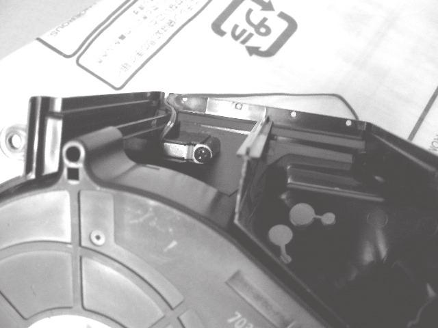
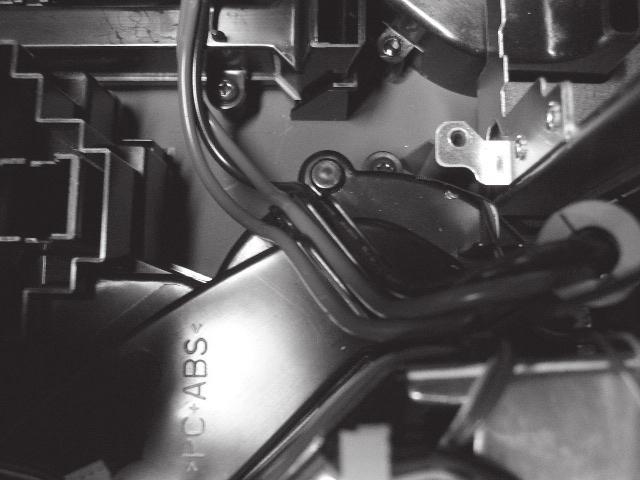
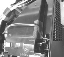
21 6- Before Replacing The LCD/Lens Prism CP-A / ED-A0 / ED-A (AB-0) You should not replace separately the parts of the liquid crystal LCD/Lens prism because it works properly only when used together. Therefore, regarding these parts, you can either replace part, LCD/Lens prism assembly, or send the whole unit LCD/Lens prism assembly back to HITACHI, where we will replace the malfunctioning part, recondition the device and send it back to you. Reset the PANEL TIME whenever you changed the LCD/LENS prism assembly. With reference to the PANEL TIME, see the section 6- HIDDEN SERVICE MENU in this manual. Do not disassemble the unit because replacement of separate parts is not possible. HITACHI 6- Cleaning up dust from panels and optical filters WARNING Wear sunglasses to protect your eyes when you maintain the projector with its lamp on.. Preparation Please prepare cleaning tools and materials as follows. And prepare relatively clean room not to work in additional dust, while removing operation. () Swab for cleaning : P#: NX, "Cotton stick BB-0" () Air duster (Dust blower, spray can) () Vacuum cleaner. Disassemble and setting up. () Turn off the projector, and unplug the power cord. () Remove the lamp cover and upper case, according to the disassembling diagram of chapter 8.

 Disconnect the LCD panel flexible cables and unscrew PWB assembly")


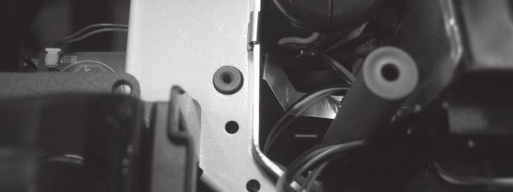
22 CP-A / ED-A0 / ED-A (AB-0) () Remove the mirror cover and the bracket. Remove screw, then remove the bracket Remove screw, then remove the mirror cover. Never damage surface of mirror. () Disconnect the LCD panel flexible cables and unscrew PWB assembly MAIN to make it free. Remove screws Flexible cables of LCD panel Remove screws Never put the heavy stress to the main board. Otherwise, connectors will be damaged. WARNING () Press and hold the switch S80 using an insulator during maintenance. () Keep the unscrewed wires away from all of electric parts.
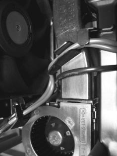
23 CP-A / ED-A0 / ED-A (AB-0). Maintenance point PANEL Actual formation HOLDER OPTICAL FILTER OPTICAL FILTER Each color part has same construction.by using swab and air duster, you can easily remove dust from panel and optical filter.. Cleaning the panels and optical filters () Turn on the set and lit on the lamp. () By using swab and air duster, remove the dust. Focusing dust makes you check the dust on screen. Panel While removing the dust, separated dust will be blown off by air cooling system. Please pay attention not to damage panels and optical filters. Bend the top of SWAB a little if it is hard to insert the SWAB. Holder Optical filter. Re-assembly () Turn off the set and unplug the power cord. () Remove an insulator from S80. () Screw down the PWB assembly MAIN and connect the LCD panel flexible cables to the PWB assembly MAIN. () Re-assemble the set. () While re-assembling, please clean the intake filter by using a vacuum cleaner.
24 CP-A / ED-A0 / ED-A (AB-0) 6- Battery WARNING Always handle the batteries with care and use them only as directed. Improper use may result in battery explosion, cracking or leakage, which could result in fire, injury and/or pollution of the surrounding environment. Be sure to use only the batteries specified. Do not use batteries of different types at the same time. Do not mix a new battery with used one. Make sure the plus and minus terminals are correctly aligned when loading a battery. Keep a battery away from children and pets. Do not recharge, short circuit, solder or disassemble a battery. Do not allow a battery in a fire or water. Keep batteries in a dark, cool and dry place. If you observe a leakage of a battery, wipe out the flower and then replace a battery. If the flower adheres your body or clothes, rinse well with water immediately. Obey the local laws on disposing the battery. Use the batteries included in this product or two new batteries of the specified type: HITACHI MAXELL, part number LR6 or R6P.. Remove the battery cover. Slide back and remove the battery cover in the direction of the arrow.. Insert the batteries. Align and insert the two batteries according to their plus and minus terminals as indicated in the remote control.. Close the battery cover. Replace the battery cover in the direction of the arrow and snap it back into place. The signal settings for the remote control transmitter and the projector s remote sensor can be changed. If the remote control does not function properly try changing the signal setting. Changing the signal setting for the remote control transmitter () Setting (FREQ. : NORMAL) Simultaneously press and hold the MUTE and RESET buttons for about seconds. () Setting (FREQ. : HIGH) Simultaneously press and hold the MAGNIFY OFF and ESC buttons for about seconds. Setting is the factory default setting. When the batteries are removed from the remote control, user-specified settings are saved for about half a day. If the batteries are removed from the remote control for longer than half a day, the remote will reset to Setting. Changing the signal setting for the projector s remote sensor Switch between Setting and using the SERVICE/REMOTE FREQ. item found in OPTION MENU. Use the / button to change the Projector's remote sensor setting. :NORMAL :HIGH Items with a checkmark are on. The factory default setting is for both :NORMAL and :HIGH to be on. If the remote control does not function correctly set this to either only or only. Neither can be turned off at the same time. NOTE: The remote control will not function properly if the remote control transmitter settings and the projector's remote sensor settings are not the same.
25 CP-A / ED-A0 / ED-A (AB-0) 6- Air filter WARNING Before caring, make sure the power switch is off and the power cable is not plugged in, then allow the projector to cool suffi ciently. The care in a high temperature state of the projector could cause an electric shock, a burn and/or malfunction to the projector. Use only the air fi lter of the specifi ed type. Do not use the projector with the air fi lter and the fi lter cover removed. It could result in a fi re and/or malfunction to the projector. The air fi lter should be cleaned periodically. If the air fi lter becomes clogged by dust or the like, internal temperatures rise and could cause a fi re, a burn and/or malfunction to the projector. NOTE Please replace the air fi lter when it is damaged or too soiled, and also when you replace the lamp. Please reset the fi lter time only when you have cleaned or replaced the air fi lter, for a suitable indication about the air fi lter. The projector may display the message such as CHECK THE AIR FLOW or turn itself off, to prevent the internal heat level rising. If the air fi lter becomes clogged by dust or the like, internal temperatures rise and could cause a fi re, a burn and/or malfunction to the projector. When the indicators or a message prompts to clean the air filter, clean the air fi lter as soon as possible. Please check and clean the air fi lter periodically, even if there is no message.please replace the air fi lter when it is damaged or too soiled. And also when you replace the lamp, please replace the air filter. An air filter of specified type will come together with a replacement lamp for this projector.. Turn the projector off and unplug the power cord from the power outlet. And cool the projector down by leaving it for a while as it is.. When the projector is suspended from the ceiling, apply the vacuum cleaner to and around the fi lter cover fi rst, to prevent penetration of dust or the like.. Use the vacuum cleaner on and around the fi lter unit. Filter unit. Slide the fi lter unit upward to take it off from the projector.. Use the vacuum cleaner on the intake vents of the projector. 6. Use the vacuum cleaner on the cover side of the filter unit. Do not vacuum the air-filter directly, since the cleaner may inhale the air-filter. When the air-filter is damaged or too soiled, prepare the new filter unit. Intake vents 7. Make sure that there is the air-fi lter inside, then slide the fi lter cover into place. 8. Plug in and restart the projector. Then, reset the fi lter time (which is the time counter for the air-fi lter use). () Press the or button on the projector or the MENU button on the remote control. The EASY MENU appears. () Point at the FILTER TIME in the menu using the or button, then press the button. A dialog appears. () Press the button to select the RESET on the dialog. It performs resetting the fi lter time.
26 CP-A / ED-A0 / ED-A (AB-0) 6-6 Lamp WARNING The projector uses a high-pressure mercury glass lamp. The lamp can break with a loud bang, or burn out, if jolted or scratched, handled while hot, or worn over time. Note that each lamp has a different lifetime, and some may burst or burn out soon after you start using them. In addition, when the bulb bursts, it is possible for shards of glass to fly into the lamp housing, and for gas containing mercury to escape from the projector s vent holes. About disposal of a lamp This product contains a mercury lamp; do not put it in the trash. Dispose of in accord with environmental laws. For lamp recycling, go to (in the US) For product disposal, contact your local government agency or (in the US) or (in Canada). Disconnect the plug from the power outlet HIGH VOLTAGE HIGH TEMPERATURE HIGH PRESSURE If the lamp should break (it will make a loud bang when it does), unplug the power cord from the outlet. Note that shards of glass could damage the projector s internals, or cause injury during handling. If the lamp should break (it will make a loud bang when it does), ventilate the room well, and make sure not to breathe the gas that comes out of the projector vents, or get it in your eyes or mouth. Before replacing the lamp, turn the projector off and unplug the power cord, then wait at least minutes for the lamp to cool suffi ciently. Handling the lamp while hot can cause burns, as well as damaging the lamp. Never unscrew except the appointed (marked by an arrow) screws. Do not open the lamp cover while the projector is suspended from above. This is dangerous, since if the lamp s bulb has broken, the shards will fall out when the cover is opened. Do not use the projector with the lamp cover removed. At the lamp replacing, make sure that the screws are screwed in fi rmly. Loose screws could result in damage or injury. Use only the lamp of the specified type. If the lamp breaks soon after the fi rst time it is used, it is possible that there are electrical problems elsewhere besides the lamp. Handle with care: jolting or scratching could cause the lamp bulb to burst during use. Using the lamp for long periods of time could cause it dark, not to light up or to burst. When the pictures appear dark, or when the color tone is poor, please replace the lamp as soon as possible. Do not use old (used) lamps; this is a cause of breakage. Do not break up the lamp to replace because the structual parts broken up is unavailable. 6
27 CP-A / ED-A0 / ED-A (AB-0) Replacing the Lamp A lamp has a fi nite product life. Using the lamp for long periods of time could cause the pictures darker or the color tone poor. Note that each lamp has a different lifetime, and some may burst or burn out soon after being started using.. Turn the projector off and unplug the power cord from the power outlet. And cool the projector down by leaving it for about minutes as it is.. Loosen the screw (marked by arrow) of the lamp cover, and then slide the lamp cover to the side to remove it. Lamp cover. Loosen the screws (marked by arrows) of the lamp, and slowly pick up the lamp by the handles.. Insert the new lamp, with cautions not to touch the inside of the lamp house. When inserting, pay attention to the socket position fi rst, and to the pins for positioning next.. Tighten fi rmly the screws of the lamp that are loosened in the previous process to lock it in place. 6. Slide the lamp cover into place and fi rmly tighten the screw of the lamp cover. 7. Plug in and restart the projector. Then, reset the lamp time (which is the time counter for the lamp use). () Press the or button on the projector or the MENU button on the remote control. The EASY MENU appears. () Point at the Go to Advanced Menu in the menu using the or button, then press the button. MENU appears. () Pointed at the OPTION in the left column using the or button, then press the button. The cursor moves to the right column. () Pointed at the LAMP TIME using the or button, then press the button. A dialog appears. () Press the button to select the RESET on the dialog. It performs resetting the lamp time. Screw Lamp house (inside of the lamp cover) Pin for positioning Pin for positioning Socket Screw CAUTION Do not touch any inner space of the projector, while the lamp is taken out. NOTE Please reset the lamp time only when you have replaced the lamp, for a suitable indication about the lamp. 7
28 CONTROL USB AUDIO IN S-VIDEO AUDIO IN AUDIO OUT LAN CONTROL USB AUDIO IN S-VIDEO AUDIO IN AUDIO OUT LAN 6-7 Caring for the mirror and lens CP-A / ED-A0 / ED-A (AB-0) If the projection mirror or lens is flawed, soiled or fogged, it could cause deterioration of display quality. Please take care of the mirror and lens, being cautious of handling.. Turn the projector off and unplug the power cord from the power outlet. And cool the projector down by leaving it for a while as it is.. The lens door can be opened manually. Please hold both side of the lens door and slowly open it until it is locked with clicking sound.. Wipe softly the mirror and lens with a cleaning cloth for lens on the market, being careful not to give any damage on the mirror and lens. For around edge of the mirror and lens where might be diffi cult to be wiped out, please use an air blower for cameras on the market to clean up. COMPUTER OUT COMPUTER IN COMPUTER IN Y CB/PB CR/PR VIDEO L R COMPUTER OUT COMPUTER IN COMPUTER IN Y CB/PB CR/PR VIDEO L R. To close the lens door properly, please take the following procedure. () Plug in the projector. () Turn on the power switch. Even though the lens door starts to close, it might not be closed properly. () Press the STANDBY/ON button, so that the lamp starts to light up. () After the POWER indicator turns to steady green, press the STANDBY/ON button twice to turn off the projector. The lens door will close properly. Cleaning cloth Blower NOTE When the lens door is closed manually, it may not shut properly. WARNING Before caring for the projection mirror and lens, turn the projector off and unplug the power cord, then cool the projector suffi ciently. Do not use a vacuum cleaner to clean the projection mirror or lens, since it might give some damage. Do not use cleaners or chemicals other than those specifi ed in this manual. Especially the mirror has to be paid special attention, since these materials might give serious damage on the mirror. CAUTION Be careful not to pinch your fi nger with the lens door, to prevent an injury. 8
29 6-8 Using the cable cover CP-A / ED-A0 / ED-A (AB-0) Utilize the cable cover as the guard and blind for the connecting parts.. Connect the signal cables and the power cord to the projector fi rst. Cable cover. Attach the cable cover to the projector, uniting the interlocking parts. LAN COMPUTER OUT COMPUTER IN COMPUTER IN AUDIO USB S-VIDEO OUT AUDIO IN Y CB/PB CR/PR. Tighten the screw to fi x the cable cover. CONTROL VIDEO L R AUDIO IN. Connect the other ends of the cables to other devices, and plug the power cord to the power outlet. Interlocking parts Screw Screw driver CAUTION Be careful not to pinch the cables in the cable cover, to prevent damage to the cables. 6-9 Other care WARNING Before caring, make sure the power switch is off and the power cable is not plugged in, and then allow the projector to cool suffi ciently. The care in a high temperature state of the projector could cause a burn and/ or malfunction to the projector. Avoid wetting the projector or inserting liquids in the projector. It could result in a fi re, an electric shock, and and/or malfunction to the projector. Don t put a container containing water, cleaner or chemicals near the projector. Don t use aerosols or sprays. CAUTION Please take right care of the projector according to the following. Incorrect care could cause not only an injury but adverse influence such as discoloration, peeling paint, etc. Do not use cleaner or chemicals other than those listed below. Do not polish or wipe with hard objects. Inside of the projector In order to ensure the safe use of the projector, it needs to clean and inspect the projector about once a year. Caring for the cabinet and remote control Incorrect care could have adverse influence such as discoloration, peeling paint, etc.. Turn the projector off, and unplug the power cord. Allow the projector to cool sufficiently.. After making sure that the projector is cool adequately, lightly wipe with gauze or a soft cloth. If soiling is severe, dip soft cloth in water or a neutral cleaner dilute in water, and wipe lightly after wringing well. Then, wipe lightly with a soft, dry cloth. 9
30 CP-A / ED-A0 / ED-A (AB-0) 6-0 Notice of AUTO adjustment Use of AUTO adjustment with the image through RGB input optimizes V_POSI, H_POSI, H_SIZE and H_PHASE automatically. In case that projected image has dark tone around its peripheral, AUTO operation sometimes makes artifacts in the image, shifts capture area and so on. Those failures are caused by period of image data is not exactly distinguished to period of blanking on signal processing. To avoid such phenomena, AUTO function should be used with the full size picture that has bright tone on its peripheral. Image when AUTO operates correctly Image when AUTO fails. Noting image of top or bottom lines. Shift of the image to East or West. Artifacts on image. Etc. Note ) The phenomenon at the failure of AUTO adjustment depends on resolution of input source, scene of picture etc. ) There is no failure above in AUTO with video source through VIDEO, S-VIDEO or COMPONENT input. The reason is why recognition of input signal s standard does not need to search the capture range from input signal itself. 0
31 CP-A / ED-A0 / ED-A (AB-0) 6- How to inactivate the security functions This projector is equipped with security functions. ()MyScreen PASSWORD The MyScreen PASSWORD function can be used to prohibit access to the MyScreen function and prevent the currently registered MyScreen image from being overwritten. ()PIN LOCK PIN LOCK is a function which prevents the projector from being used unless a registered Code is input. ()Transition detector Transition detector is a function which prevents the projector from being used if the setting condition of the projector (normal use or ceiling mounted or table top use) and mirror setting is not same with recorded. Transition Detector Alarm ()MY TEXT This item allows you to display your own message (MY TEXT) on the START UP screen and INPUT- INFORMATION. It can be protected by a password to prevent it from being overwritten. It is possible to inactivate all security functions temporarily with following procedures. () Go to SECURITY on OPTION Menu and press the button. Then, ENTER PASSWORD box will be displayed. (The BOX will be displayed by pressing the [MENU] button (remote) or [ / ] button (keypad) when Transition Detector Alarm is displayed.) ENTER PASSWORD box () Press the [Magnify off] button once, then press [Magnify off] button of remote for second or more to display SERVICE PASSWORD box. SERVICE PASSWORD box () Enter the Life Key (MENU,, KEYSTONE, ). Then all security functions will be inactivated temporarily. Note: The Life key can be used up to 0 times. The key cannot be used thereafter. If the Life key cannot be used, see the paragraph of SECURITY in the User s Manual. The frequency in which Life key is input will be set to 0 after the registered code is input. The SECURITY Menu can not be operated if the SECURITY PASSWORD was released by Life key. The Mirror, Keystone and Auto keystone are not memorized though they are possible to operate if Transition Detector was released by Life key. The MyScreen Lock on SCREEN Menu keeps TURN ON if MyScreen PASSWORD was set when SECURITY PASSWORD was released by Life key.
32 CP-A / ED-A0 / ED-A (AB-0) 6- PIN LOCK System If the following PIN BOX menu appears after power on the projector, the PIN LOCK system has been activated. Under such a condition, key operations and signal displaying are inhibited. To open the PIN LOCK system, we need to input the correct digits PIN CODE. If correct PIN CODE is not input in min., the lamp will be automatically turned off. PIN BOX Returning repaired unit Use the Master PIN code. See the paragraph of Releasing the PIN LOCK system inactivation. Swap unit/returned unit Release all security systems. See the paragraph of the PIN LOCK system inactivation. Releasing the PIN LOCK System When the PIN BOX menu is displayed, sequentially enter the codes with remote controller as follows. In accordance with remote controller button entry, mark appears in the PIN BOX menu. Master PIN codes st entry code: Press the MENU button. nd entry code: Press the button. rd entry code: Press the KEYSTONE button. th entry code: Press the button. Note: The Master PIN codes can be used up to 0 times. The codes cannot be used thereafter. If the Master PIN codes cannot be used, see the paragraph of the PIN LOCK system inactivation. The PIN LOCK System inactivation. When the PIN BOX menu is displayed, press RESET for seconds or more in order to get the ID Inquiring Code. PIN BOX Inquiring Code Inquiring Code PIN BOX (ID Inquiring Code). Send HITACHI sales company the Inquiring code (0 digits) to inquire the correct PIN code.. With the PIN BOX menu displayed, input the correct PIN code. Enter the correct PIN CODE that HITACHI sales company informed.. Open menu and select TURN OFF from the PIN LOCK items in the SECURITY menu. Then the PIN BOX menu appears. Password is required to display the Security Menu. See the Security in OPTION menu: User s Manual - Operating Guide.. Input the correct PIN code in the PIN BOX menu. 6. And then, PIN LOCK will be set to TURN OFF. 7.Inactivate the MyScreen PASSWORD and Transition Detector too. And reset the Security Password to the [0]. See the Security in OPTION menu: User s Manual - Operating Guide.
33 CP-A / ED-A0 / ED-A (AB-0) 6- Related Messages When the unit s power is on, messages such as those shown below may be displayed. When any such message is displayed on the screen, please respond as described below. Although these messages will be automatically disappeared around several minutes, it will be reappeared every time the power is turned on. Message NO INPUT IS DETECTED *** SYNC IS OUT OF RANGE *** fh *****khz fv *****Hz INVALID SCAN FREQ. *** CHECK THE AIR FLOW REMINDER ***HRS PASSED AFTER THE LAST FILTER CHECK. FILTER MAINTENANCE IS ESSENTIAL TO REMOVE WARNING MESSAGE, RESET FILTER TIMER. SEE MANUAL FURTHER INFO. Description There is no input signal. Please confi rm the signal input connection, and the status of the signal source. The horizontal or vertical frequency of the inputted signal is outside of the response parameters of this unit. Please confi rm the specs for this unit or the signal source specs. An improper signal is input. Please confi rm the specs for your projector or the signal source specs. The internal portion temperature is rising. Please turn the power OFF, and allow the unit to cool down at least 0 minutes. After having confi rmed the following items, please turn the power ON again. Is there blockage of the air passage aperture? Is the air fi lter dirty? Does the peripheral temperature exceed C? If the same indication is displayed after the remedy, please set FAN SPEED of the SERVICE item in the OPTION menu to HIGH. A note of precaution when cleaning the air filter. Please immediately turn the power OFF, and clean or change the air filter by referring to the Air Filter section of this manual. After you have cleaned or changed the air fi lter, please be sure to reset the fi lter timer.
34 6- Regarding the indicator lamps CP-A / ED-A0 / ED-A (AB-0) Lighting and flashing of the POWER indicator, the LAMP indicator, and the TEMP indicator have the meanings as described in the table below. Please respond in accordance with the instructions within the table. POWER indicator Lighting In Orange Blinking In Green Lighting In Green Blinking In Orange Blinking In Red Blinking In Red or Lighting In Red Blinking In Red or Lighting In Red Lighting In Red Blinking In Red or Lighting In Red Blinking In Red or Lighting In Red Lighting In Green Lighting In Green LAMP indicator Turned off Turned off Turned off Turned off Lighting In Red Blinking In Red Turned off Turned off Turned off TEMP indicator Turned off Turned off Turned off Turned off (discretionary) (discretionary) Turned off Turned off Turned off Blinking In Red Lighting In Red Alternative blinking in Red Simultaneous blinking in Red The projector is in a standby state. Description The projector is warming up. Please wait. The projector is in an on state. Ordinary operations may be performed. The projector is cooling down. Please wait. The projector is cooling down. A certain error has been detected. Please wait until the POWER indicator finishes blinking, and then perform the proper measure using the item descriptions below. The lamp does not light, and there is a possibility that interior portion has become heated. Please turn the power off, and allow the projector to cool down at least 0 minutes.after the projector has suffi ciently cooled down, please make confi rmation of the following items, and then turn the power on again. Is there blockage of the air passage aperture? Is the air fi lter dirty? Does the peripheral temperature exceed ºC? If the same indication is displayed after the remedy, please change the lamp referring to the section Lamp. The lamp cover has not been properly fixed (attached). Please turn the power off, and allow the unit to cool down at least minutes. After the projector has suffi ciently cooled down, please make confi rmation of the attachment state of the lamp cover. After performing any needed maintenance, turn the power on again. The lens door is not opened or closed properly. One of the followings has been happened. The lens door is not opened properly, when the projector is turned on. The lens door is not closed properly, when the projector is turned off. The lens door position is shifted, while the projector is working. Restart the projector, after confirming that there is nothing that the lens door hits while opening or closing. The cooling fan is not operating. Please turn the power off, and allow the unit to cool down at least 0 minutes. After the projector has sufficiently cooled down, please make confirmation that no foreign matter has become caught in the fan, etc., and then turn the power on again. If the same indication is displayed after the remedy, please replace a fan. There is a possibility that the interior portion has become heated. Please turn the power off, and allow the unit to cool down at least 0 minutes. After the projector has sufficiently cooled down, please make confirmation of the following items, and then turn the power on again. Is there blockage of the air passage aperture? Is the air fi lter dirty? Does the peripheral temperature exceed C? If the same indication is displayed after the remedy, please set the FAN SPEED of the SERVICE item in the OPTION menu to HIGH. There is a possibility that the interior portion has become overcooled. Please use the unit within the usage temperature parameters ( C to C). After the treatment, resent the power to ON. If the same indication is displayed after the treatment, please make sure that the proper cables are connected to each of connectors E0, E0 and E0 on the PWB assembly MAIN. It is time to clean the air filter. Please immediately turn the power OFF, and clean or change the air fi lter referring to the section Air Filter. After cleaning or change the air fi lter, please be sure to reset the fi lter timer. After the remedy, resent the power to ON. NOTE When the interior portion has become overheated, for safety purposes, the power source is automatically turned off, and the indicator lamps may also be turned off. In such a case, press the (OFF) side of the power switch, and wait at least minutes. After the projector has sufficiently cooled down, please make confi rmation of the attachment state of the lamp and lamp cover, and then turn the power on again.
35 6- HIDDEN SERVICE MENU HIDDEN SERVICE AIR-SENSOR EXECUTE LAMP ALARM NONE STARTUP TYPE PANEL TIME h LONG KEY TURN OFF SOFT RESET AIR - SENSOR Execute this item to adjust the air sensor. CP-A / ED-A0 / ED-A (AB-0) To display the OSD for HIDDEN SERVICE MENU set up. By the control panel. Display the Advanced menu by the MENU button.(if EASY MENU appears, choose Go to Advanced menu to display ADVANCED MENU.). Select the OPTION on the menu.. Continue press the button [ ] fi rst, then press the button [ ] together with INPUT, and hold for seconds. By the remote control transmitter. Display the menu by the MENU button. (If EASY MENU appears, choose Go to Advanced menu to display ADVANCED MENU.). Select the OPTION on the menu.. Press the MAGNIFY OFF button. Next hold the MAGNIFY OFF button for seconds. LAMP ALARM Select the lamp alarm level. Level Level None Level shows three kinds of lamp-messages according to the LAMP TIME count. Level shows one kind of lamp-message according to the LAMP TIME count. None shows no lamp-messages. It is the factory default setting. STARTUP TYPE Select the startup screen type. : shows Hitachi Logo : No Hitachi Logo PANEL TIME Use time of LCD panel. Reset the PANEL TIME whenever you changed the LCD/LENS prism assembly. LONG KEY Select the remote control button operation mode. NORMAR LONGThe LONG allows to control the projector with the remote control unit when you hold a button of it for about seconds, and makes MY BUTTON / function as LONG KEY DISABLE/LONG KEY ENABLE compulsorily. If you use these buttons to control the projector as you assigned with the MY BUTTON menu, set to the NORMAL. SOFT RESET If this is executed, all of the user data is initialized.never use it when not required. 6-6 RUN TIME window Set operating time display method (accumulated lamp time display method). Select OPTION from the Advanced menu, then place the cursor on the LAMP TIME.. Press the [ ], [ENTER] or [RESET] button.. Press the [Reset] button once, then press [KEYSTONE] button of the remote control for seconds or more to display the screen shown below. (The menu will close after 0 seconds if there are no further operations.). Use [ ] or [ ] to select the usage status number. (The usage status is as shown below.) Ex. RUNTIME window for CP-A RUN TIME LAMP h Lamp time NORMAL 000h Lamp time(normal) WHISPER h Lamp time(whisper) AC 000h AC energizing time On Number of times on Off 0 Number of times off No.0 Usage status number(see be Usage status number 0... Total usage status... Current usage status... Usage status before first reset... Usage status before second reset 9... Usage status before eighth reset


36 CP-A / ED-A0 / ED-A (AB-0) 7. Wiring diagram Area of Importance YSA7A-** 7 Area of Importance The operations with this symbol have implications with laws/standards. It is possible to be in violatio n of these laws/standards in the case that these o perations are not carried out according to the instr uctions. Assemble according to the operation instr uctions. Wiring diagram 6
Attach the CNGD. ()Attach the FEB to the CNAC.")


37 CP-A / ED-A0 / ED-A (AB-0) Wi ring of the circuit power supply ()Attach the CNGD. ()Attach the FEB to the CNAC. ()Attach the lamp fan cable to the power unit case with tape. CNAC GND FEB CNPFC Attach the FEB to CNAC. Make sure to completely lockthe hook when attaching the FEB. Area of Import ance Attach the CNGD to the bracket with screw. Wiring diagram ZTP Attach the lamp fan cable to the lamp fan with tape. Confirm cable colors are red, black and white. Nitto tape:no. Width:9mm Length:0mm 7

Attach the CNGD to the ballast shield and the ballast case.")


38 CP-A / ED-A0 / ED-A (AB-0) Wiring of the ballast ()Attach the CNBAR and CNLAP to the ballast board. ()Attach the sensor(inside) to the ballast case. ()Attach the CNGD to the ballast shield and the ballast case. CNLAP Sensor (inside) CNBAR Connect the CNBAR completely. Make sure to lock the CNLAP completely. It s hard to check later. Attach the sensor (inside) to the ballast case as shown in the diagram. Pass the connector through the slit. It s hard to check later. CNGD Attach the CNGD to the bottom of the ballast shield Pass the CNGD through the slit of ballast case. Wiring diagram 8


39 CP-A / ED-A0 / ED-A (AB-0) ()Wiring of the CNLAP and CNBAR. Attach the CNLAP to the ballast board. Then, pass the CNLAP through the slit of the case. Pass the CNBAR through the hole in the upper part of case. Then, hang the cable to the hook in the side of case. Wiring diagram CNBAR ZTP ZTP Attach the CNBAR to the ballast case with tape. Nitto tape:no. Width:0mm Length:0mm 9

")

40 CP-A / ED-A0 / ED-A (AB-0) Wiring diagram 0


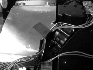
41 CP-A / ED-A0 / ED-A (AB-0) Wiring of the main board. ()Attach the CNVID and the CNAU to the main board. ()Attach the CNVID and the CNAU to the input board. Connect main board and input board by CNAU and CNVID. Put excessive length to I/O metal side.. CNAU CNVID Preparation of remote board ()Attach the CNRC CNRC Preparation of speaker box () Pass the speaker cable through the slit at the left side of the speaker box. Attach speaker cable with tape. Do not put speaker cable on contact face of speaker box. Otherwise, cable will be pinched by box and bottom case. tape speaker slit Contact face to bottom case Wiring diagram 6

Style the speaker cable along the speaker box like the diagram.")
42 CP-A / ED-A0 / ED-A (AB-0) Attaching the speaker box and panel duct ()Pass the speaker cable under the remote board. Confirm sirocco fan cables color are yellow, red and black. Sirocco fan is in the center of bottom case. Wiring diagram 7 speaker ()Style the speaker cable along the speaker box like the diagram. Never make the cable slack. ()Attach the remote board. Make sure not to pinch the cable by remote board.
 to the bottom case, then wire the CNPFC. ()Wire the TSW.")


43 CP-A / ED-A0 / ED-A (AB-0) Attaching the power unit (circuit) ()Attach the power unit (circuit) to the bottom case, then wire the CNPFC. ()Wire the TSW. CNPFC Hang the CNPFC to circuit power unit hook. Make the 0mm excessive length at the power unit side. You can easily remove the circuit power unit. Wiring diagram 8 Make sure not to pinch the cables when you attach the power unit block to the bottom case. Wire the exhaust fan cable hanging to the hook of the power unit.

 Wire the CNAC on the CNGD.")
 Attach the cover to the AC inlet board.")


44 CP-A / ED-A0 / ED-A (AB-0) Attaching the inlet () Attach the CNGD to the AC inlet board. () Pass the CNGD between the bottom case rib and the ditch. () Wire the CNAC on the CNGD. Put the FEB at the right position like the diagram. () Attach the cover to the AC inlet board. Wire CNGD And CNAC between dot lines. Do not cross each other. Otherwise, cables will be pinched by Mirror unit. Put the FEB to this position. Make the excessive length. Wiring diagram 9 Style the CNGD like the diagram to take out the inlet board from the bottom case. Attach the cover to the AC inlet first. Then, take the cable out from the side of the case.

")

45 CP-A / ED-A0 / ED-A (AB-0) Wiring diagram 0

")

46 CP-A / ED-A0 / ED-A (AB-0) Wiring diagram 6

")

47 CP-A / ED-A0 / ED-A (AB-0) Make sure to completely lock the hook when Wiring diagram 7

")


48 CP-A / ED-A0 / ED-A (AB-0) Wiring diagram 8


49 CP-A / ED-A0 / ED-A (AB-0) Wiring diagram Lamp fan Electric Mirror motor 9
50 8. Disassembly diagram CP-A / ED-A0 / ED-A (AB-0) PWB assembly MAIN 7 UPPER CASE assembly (See Notice ) PWB assembly MAIN 8 Mirror cover reverse side 6 8 Terminal side LCD/LENS/PRISM MIRROR/ DICHROIC OPTICS UNIT LCD/LENS/PRISM MIRROR/ DICHROIC OPTICS UNIT (See Notice ) MIRROR assembly (See Notice ) 9 8 6(See Notice 8) 9 0 (See Notice 6) Refer to the 9. Replacement Parts list. 0
51 CP-A / ED-A0 / ED-A (AB-0) Power unit BALLAST assembly (See Notice,9) LAMP assembly 6 DUCT / FAN (See Notice 7) Power unit BALLAST assembly 9 DUCT / FAN 0 7 SPEAKER assembly 0 7 SPEAKER assembly BOTTOM CASE assembly 9 Refer to the 9. Replacement Parts list. 6
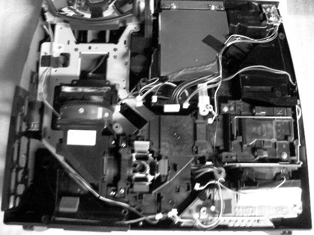
52 CP-A / ED-A0 / ED-A (AB-0) Notice The step of the disassembly / The step of the assembly. Disassemble the projector in order of,,,,, 6, 7, 8 and 9 as shown in the diagram.assemble the projector in order of 9. 8, 7, 6,,,, and as shown in the diagram. Mirror Cover Lamp Unit Main board Tighten this screw first Cooling duct Earth bracket Wind shield Earth bracket Earth bracket 6 Ballast 8 Power Unit (Circuit) 7 Optical Unit 9 Other parts Jig for assembling Jig for assembling you have to use this Jig when you assemble the projector.


53 CP-A / ED-A0 / ED-A (AB-0) Notice. Detach and attach the upper case. Follow the procedure below to detach and attach the upper case. When disassembling a. Remove the Lamp door. CAUTION The lamp door must be removed before the upper case when disassembling the machine. If the upper case is detached with the lamp door installed, the MAIN board might be damaged. Lamp door Loosen this screw b. Remove 9 screws on the bottom and screw on the side to detach the upper case. CAUTION Put the projector on soft sheet when you tighten / remove the screws on the bottom. This screws 9 screws
54 CP-A / ED-A0 / ED-A (AB-0) When assembling a. Tighten 9 screws on the bottom and screw on the rear after attaching the upper case with the lamp door separated. In order not to make a gap between the upper and the bottom cases, tighten this screw while pressing down the upper case in the direction of the arrow. Be careful not to bend the outside casing.(torque: n m) Tighten this screw b. Attach the Lamp door. Lamp door CAUTION Tighten this screw using a manual screwdriver.


55 CP-A / ED-A0 / ED-A (AB-0) Detach the upper case CAUTION Detach the lamp door, and remove the bottom case screws and the side panel screws before you detach the upper case. Detach the rear part of upper case. Do not open mirror. Lift the rear part of upper case about cm. Lift the side part of upper case to detach while pushing the rear part to front. rear front cm side Lift the mirror until mirror makes clutch sound. Then, release your hand. Mirror will be half opening. Half opening Detach the upper case from bottom case. Paints will peel off CAUTION When you detach the upper case, keep the mirror with your hand. Never touch the surface of the mirror. Make sure not to touch the side edge of mirror and edge of upper case. Otherwise, paints will peel off.


56 CP-A / ED-A0 / ED-A (AB-0) Attach the upper case Make the mirror half opening. Then, attach the upper case. Never damage the Main board by upper case boss when you attach upper case. Boss Main board Close the mirror. Attach the front part of upper case first. Attach side parts of upper case and bottom case completely. Attach the rear part of upper case next. If it is hard to attach, look the side of projector. Combination of the side part might be wrong. Check circle area in the diagram. side front rear 6
57 CP-A / ED-A0 / ED-A (AB-0). Attaching the Engine unit Assy Put the Engine unit Assy on the bottom case, and tighten screws in order of,,,, and 6 as shown in the diagram.. Attaching the mirror cover Attach the two mirror covers to the mirror, and tighten screws in order of,, and as shown in the diagram. View point from A 7

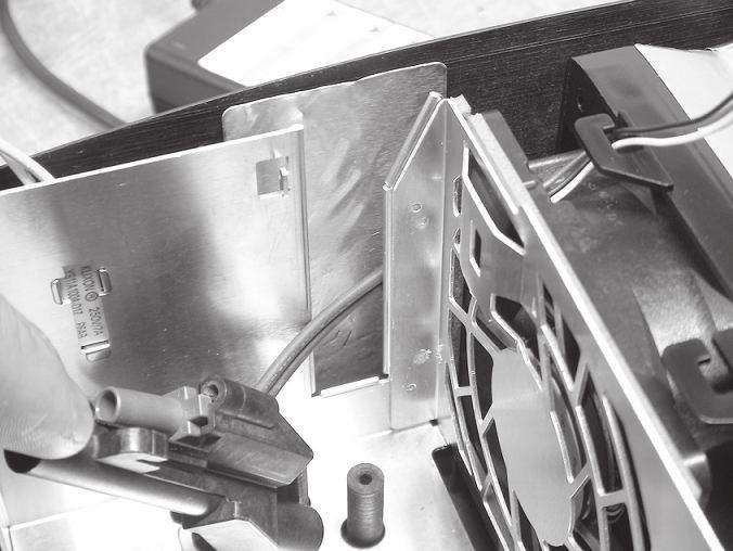
Disassembling/Assembling Dichroic optics unit Remove screws to detach the Dic")

58 CP-A / ED-A0 / ED-A (AB-0). Disassembling / Assembling the Optics Unit Follow the procedure below to disassemble / assemble the Optics Unit. ()Disassembling/Assembling Dichroic optics unit Remove screws to detach the Dic hroic optics unit from bottom bracket. Never remove the other screws. Tighten screws to attach the Dichr oic optics unit to bottom bracket. Meter screw Tapping screw Combine two parts of dichroic unit to part of lens. part of lens parts of dichroic unit 8


59 CP-A / ED-A0 / ED-A (AB-0) ()Attaching the Lenz to the bottom bracket Combine two parts of lens to part of bottom bracket. part of Engine base plate parts of lens Tighten screws to attach A LCD/LENS/PRISM ASSY to Engine base plate. ()Disassembling the mirror motor and focus motor Remove black screws to detach the mirror motor. Never remove the another screws. black screws Remove screws to detach the focus motor. screws 9


 Assembling the mirror motor Stand the")
60 CP-A / ED-A0 / ED-A (AB-0) () Assembling Mirror Hinge Assy Combine two parts of Engene base plate to parts of Mirror Hinge Assy. parts of Engine base plate parts of mirror hinge Tighten screws to attach the Mirror Hinge Assy to Engine base plate from the under. screws Pull the mirror motor and detach from mirror. () Assembling the mirror motor Stand the mirror vertically. Rotation axis of the mirror will be horizontal. Axis of the mirror 60


61 CP-A / ED-A0 / ED-A (AB-0) Insert the mirror motor to the mirror. Bush rarely remain at rotation axis of mirror. Make sure to remove the bush. Combine part of motor to part of mirror. Take care the shape of combining parts. 6


 Assembly Disassembly Do not injure your")

62 CP-A / ED-A0 / ED-A (AB-0). Assembling and Disassembling the ballast Unit Assembly Disassembly Pass ballast cable Pass sensor cable combine To main board combine 6. Assembling and Disassembling the power Unit (circuit) Assembly Disassembly Do not injure your finger by edge of standing board when you connect/ disconnet CNAC and CNPFC. CNAC CNPFC Pass TSW and CNPW through this hole before you assemble the box. 6
63 CP-A / ED-A0 / ED-A (AB-0) 7. Detaching and attaching the Panel Fan Duct assembly When disassembling Remove 7 screws and unhook the panel fan duct assembly as shown in the diagram. Tx CAUTION Make sure to put 8 spacers ( parts) on the boss. Confirm that a cushion is put on duct. Otherwise, power will shut down. Release the hook cable ditch cable ditch Sirocc fan When assembling () Put the thermistor in the correct position on the Panel duct as shown in the diagram. Thermistor 6


64 8. Attaching the circuit power unit fan Never attach the fan to the wrong direction. CP-A / ED-A0 / ED-A (AB-0) Turn the cable output to the left. 9. Attaching the ballast unit fan Never attach the fan to the wrong direction. Turn the cable output to the upper. 6
 This projector")


65 CP-A / ED-A0 / ED-A (AB-0) This projector uses some sub parts for quality improvement. Do not forget these sub parts when you assemble this projector. Board fixation bracket Earth bracket Tighten with ballast box. Earth bracket Tighten with power unit box. Earth bracket Tighten with main board bracket. 6
01CP-WX3030WNetc_CO_ENG.indd
 Data Video Projector User s Manual (Concise) ModelS: 8928A/8930A/8931WA/ 8933W Information in this Guide may change due to product improvements. To obtain the latest manuals, literature, and software please
BC04 Module_antenna__ doc
 http://www.infobluetooth.com TEL:+86-23-68798999 Fax: +86-23-68889515 Page 1 of 10 http://www.infobluetooth.com TEL:+86-23-68798999 Fax: +86-23-68889515 Page 2 of 10 http://www.infobluetooth.com TEL:+86-23-68798999
OA-253_H1~H4_OL.ai
 WARNINGS Note: Read ALL the following BEFORE using this product. Follow all Guidelines at all times while using this product. CAUTION This warning indicates possibility of personal injury and material
CP-X2511N_3011N_4011N_2011N_ED-X45N
 YK No.E SERVICE MANUAL CP-XN ( CI-N ) CP-XN ( CI-N ) CP-XN ( CI-N ) CP-XN ( C-N ) ED-XN ( C-N ) Warning The technical information and parts shown in this manual are not to be used for: the development,
K301Q-D VRT中英文说明书141009
 THE INSTALLING INSTRUCTION FOR CONCEALED TANK Important instuction:.. Please confirm the structure and shape before installing the toilet bowl. Meanwhile measure the exact size H between outfall and infall
1.ai
 HDMI camera ARTRAY CO,. LTD Introduction Thank you for purchasing the ARTCAM HDMI camera series. This manual shows the direction how to use the viewer software. Please refer other instructions or contact
Logitech Wireless Combo MK45 English
 Logitech Wireless Combo MK45 Setup Guide Logitech Wireless Combo MK45 English................................................................................... 7..........................................
<4D6963726F736F667420576F7264202D2032303130C4EAC0EDB9A4C0E04142BCB6D4C4B6C1C5D0B6CFC0FDCCE2BEABD1A15F325F2E646F63>
 2010 年 理 工 类 AB 级 阅 读 判 断 例 题 精 选 (2) Computer mouse How does the mouse work? We have to start at the bottom, so think upside down for now. It all starts with mouse ball. As the mouse ball in the bottom
TX-NR3030_BAS_Cs_ indd
 TX-NR3030 http://www.onkyo.com/manual/txnr3030/adv/cs.html Cs 1 2 3 Speaker Cable 2 HDMI OUT HDMI IN HDMI OUT HDMI OUT HDMI OUT HDMI OUT 1 DIGITAL OPTICAL OUT AUDIO OUT TV 3 1 5 4 6 1 2 3 3 2 2 4 3 2 5
CANVIO_AEROCAST_CS_EN.indd
 简 体 中 文...2 English...4 SC5151-A0 简 体 中 文 步 骤 2: 了 解 您 的 CANVIO AeroCast CANVIO AeroCast 无 线 移 动 硬 盘 快 速 入 门 指 南 欢 迎 并 感 谢 您 选 择 TOSHIBA 产 品 有 关 您 的 TOSHIBA 产 品 的 详 情, 请 参 阅 包 含 更 多 信 息 的 用 户 手 册 () 安
10WX36_OG_KOR.indd
 1 3M Digital Projector WX36 2 3 40 4 7 42 7 9 14 44 14 15 15 15 50 16 16 17 17 17 60 18 18 18 18 67 20 20 21 21 22 73 22 24 25 25 82 26 28 85 85 87 89 30 90 91 33 91 94 94 95 36 99 VIDEO ASPECT MAGNIFY
 THE INSTLLING INSTRUCTION FOR CONCELED TNK Important instuction:.. Please confirm the structure and shape before installing the toilet bowl. Meanwhile measure the exact size H between outfall and infall
Preface This guide is intended to standardize the use of the WeChat brand and ensure the brand's integrity and consistency. The guide applies to all d
 WeChat Search Visual Identity Guidelines WEDESIGN 2018. 04 Preface This guide is intended to standardize the use of the WeChat brand and ensure the brand's integrity and consistency. The guide applies
CONGRATULATIONS ON YOUR PURCHASE OF OUR CAMERA This product has been carefully inspected through rigid quality control before shipment. With reasonabl
 INSTRUCTIONS MANUAL SMOKE DETECTOR COLOR, B/W CCD CAMERA CONTENTS English / Chinese PREFACE SAFETY INSTRUCTIONS FUNCTION DESCRIPTION INSTALLATION SPECIFICATIONS PR0210SDE2 Thank you very much for purchasing
E15-3D1 1. Specifications Compact 4-Way Cassette type Model name MMU- AP0071MH2UL AP0091MH2UL AP0121MH2UL AP0151MH2UL AP0181MH2UL Cooling Capacity kbt
 E15-3D1 Compact 4-Way Cassette type MMU-AP0071MH2UL MMU-AP0091MH2UL MMU-AP0121MH2UL MMU-AP0151MH2UL MMU-AP0181MH2UL Contents 1. Specifications 2. Dimensions 3. Center of gravity 4. Piping diagram 5. Wiring
10CP-CW302WN_OG_KOR_ indd
 CP-CW302WN 1 2 3 1. 2. 3. 3 1 2 4 6 97 18 102 16 6 13, 22, 52 24 24) 16 16 4 25 99 101 5 20 23 20, 105 105 105 30 30 58 10~15 6 7 23 20 23 25 26 26 24 24 19 28 62 22 19 28 62 22 27 26 29 22 30 30, 31 30,
LH_Series_Rev2014.pdf
 REMINDERS Product information in this catalog is as of October 2013. All of the contents specified herein are subject to change without notice due to technical improvements, etc. Therefore, please check
Microsoft Word - template.doc
 HGC efax Service User Guide I. Getting Started Page 1 II. Fax Forward Page 2 4 III. Web Viewing Page 5 7 IV. General Management Page 8 12 V. Help Desk Page 13 VI. Logout Page 13 Page 0 I. Getting Started
AL-M200 Series
 NPD4754-00 TC ( ) Windows 7 1. [Start ( )] [Control Panel ()] [Network and Internet ( )] 2. [Network and Sharing Center ( )] 3. [Change adapter settings ( )] 4. 3 Windows XP 1. [Start ( )] [Control Panel
Windows XP
 Windows XP What is Windows XP Windows is an Operating System An Operating System is the program that controls the hardware of your computer, and gives you an interface that allows you and other programs
Microsoft Word - 3. Vitroefication_using_EMGP.docx
 EM GP 冷 冻 样 品 制 备 实 习 教 程 (Xiaojun Huang, Gang Ji) 每 位 演 示 及 带 领 学 员 实 习 EM GP 冷 冻 样 品 制 备 的 老 师 的 材 料 清 单 : 1)15 个 GIG 载 网 2) 冷 冻 样 品 Ferritin 或 Ribosome 3)EM GP 专 用 镊 子 1 把 4)1-10ul 移 液 器,1 把 ( 移 液 器
10X21X26_OG_KOR.indd
 3M Digital Projector X21/X26 2 3 3 3 4 4 5 5 6 7 7 9 11 11 12 12 12 13 14 14 14 16 16 16 16 18 18 19 19 20 20 21 22 23 23 24 26 28 31 33 36 38 39 45 50 56 56 58 60 61 61 62 63 64 67 VIDEO ASPECT MAGNIFY
Microsoft PowerPoint - AWOL - Acrobat Windows Outlook.ppt [Compatibility Mode]
![Microsoft PowerPoint - AWOL - Acrobat Windows Outlook.ppt [Compatibility Mode]](/thumbs/96/127867671.jpg "Microsoft PowerPoint - AWOL - Acrobat Windows Outlook.ppt [Compatibility Mode]") AWOL Windows - Tips & Tricks Resolution, color depth & refresh rate Background color Service packs Disk cleanup (cleanmgr) Disk defragmentation AWOL Windows Resolution, Color Depth & Refresh Rate The main
AWOL Windows - Tips & Tricks Resolution, color depth & refresh rate Background color Service packs Disk cleanup (cleanmgr) Disk defragmentation AWOL Windows Resolution, Color Depth & Refresh Rate The main
K7VT2_QIG_v3
 ............ 1 2 3 4 5 [R] : Enter Raid setup utility 6 Press[A]keytocreateRAID RAID Type: JBOD RAID 0 RAID 1: 2 7 RAID 0 Auto Create Manual Create: 2 RAID 0 Block Size: 16K 32K
c11_10iPJ-AW250N_OG_KOR.indd
 CP-X2541WN/CP-X3041WN/CP-X4041WN CP-WX3041WN/CP-WX3541WN/CP-WX4041WN 1 2 3 4 98 2352 100 27 27 19 102 5 27 27 16 5 5 10~15 15 17 17 21 24 32 105 105 105 24 24 25 21 26 28 31 30 30 25, 62 23 20 20 23 23
1
 Application Chuck Instruction Manual Universal Ball Lock Power Chuck APPLICATION CHUCK PBL CHUCK (UNIVERSAL BALL LOCK POWER CHUCK) TABLE OF CONTENTS Keep this manual handy for easy reference as it will
Cube20S small, speedy, safe Eextremely modular Up to 64 modules per bus node Quick reaction time: up to 20 µs Cube20S A new Member of the Cube Family
 small, speedy, safe Eextremely modular Up to 64 modules per bus de Quick reaction time: up to 20 µs A new Member of the Cube Family Murrelektronik s modular I/O system expands the field-tested Cube family
國 立 政 治 大 學 教 育 學 系 2016 新 生 入 學 手 冊 目 錄 表 11 國 立 政 治 大 學 教 育 學 系 博 士 班 資 格 考 試 抵 免 申 請 表... 46 論 文 題 目 申 報 暨 指 導 教 授... 47 表 12 國 立 政 治 大 學 碩 博 士 班 論
 國 立 政 治 大 學 教 育 學 系 2016 新 生 入 學 手 冊 目 錄 一 教 育 學 系 簡 介... 1 ( 一 ) 成 立 時 間... 1 ( 二 ) 教 育 目 標 與 發 展 方 向... 1 ( 三 ) 授 課 師 資... 2 ( 四 ) 行 政 人 員... 3 ( 五 ) 核 心 能 力 與 課 程 規 劃... 3 ( 六 ) 空 間 環 境... 12 ( 七 )
Microsoft Word - HC20138_2010.doc
 Page: 1 of 7 Date: April 26, 2010 WINMATE COMMUNICATION INC. 9 F, NO. 111-6, SHING-DE RD., SAN-CHUNG CITY, TAIPEI, TAIWAN, R.O.C. The following merchandise was submitted and identified by the vendor as:
 : 205-03-311 5863 Series 0.35mm Pitch Board-to-Board Connector TABLE OF CONTENTS OUTLINE PART NAMES AND MODEL NUMBERS PART NAMES MODEL NUMBERS PRECAUTIONS IN HANDLING USING FOR BOARD-TO-BOARD CONNECTION
5in1_eDVR_Manual_Chinese.cdr
 02 English User Manual 29 User Manual Contents 2 5 6 7 8 9 10 11 12 14 17 18 19 20 21 22 23 24 25 26 27 Quick start Controls Accessories Minimum System Requirements Battery Charge Power On/Off LCM Indicator
P3B-F Pentium III/II/Celeron TM
 P3B-F Pentium III/II/Celeron TM 1999 2 3 4 5 6 7 8 9 10 11 12 1 2 3 4 5 22 21 20 19 18 17 16 15 14 13 12 11 10 9 8 7 6 13 R PS2 KBMS USB COM1 COM2 JTPWR ATXPWR PWR_FAN CPU_FAN Row 0 1 2 3 4 5 6 7 DSW JP20
iml88-0v C / 8W T Tube EVM - pplication Notes. IC Description The iml88 is a Three Terminal Current Controller (TTCC) for regulating the current flowi
 for regulating the current flowi") iml88-0v C / 8W T Tube EVM - pplication Notes iml88 0V C 8W T Tube EVM pplication Notes Table of Content. IC Description.... Features.... Package and Pin Diagrams.... pplication Circuit.... PCB Layout
iml88-0v C / 8W T Tube EVM - pplication Notes iml88 0V C 8W T Tube EVM pplication Notes Table of Content. IC Description.... Features.... Package and Pin Diagrams.... pplication Circuit.... PCB Layout
Important Notice SUNPLUS TECHNOLOGY CO. reserves the right to change this documentation without prior notice. Information provided by SUNPLUS TECHNOLO
 Car DVD New GUI IR Flow User Manual V0.1 Jan 25, 2008 19, Innovation First Road Science Park Hsin-Chu Taiwan 300 R.O.C. Tel: 886-3-578-6005 Fax: 886-3-578-4418 Web: www.sunplus.com Important Notice SUNPLUS
FILTRON 1. DC AC AC 220V 50HZ 2. 1 1 1 3. / / / / 4. 1) 2 3 4 5 6 5. 6. 7. 8. 9. / 10. 1. 2. 3. 4. 5. 6. 7. DC AC FILTRON DC AC FILTRON DC 12V 12VDC D
 2 3 4 5 6 5. 6. 7. 8. 9. / 10. 1. 2. 3. 4. 5. 6. 7. DC AC FILTRON DC AC FILTRON DC 12V 12VDC D") 2006 4 27 1 JY FILTRON 1. DC AC AC 220V 50HZ 2. 1 1 1 3. / / / / 4. 1) 2 3 4 5 6 5. 6. 7. 8. 9. / 10. 1. 2. 3. 4. 5. 6. 7. DC AC FILTRON DC AC FILTRON DC 12V 12VDC DC FILTRON AC 24VAC 24VAC AC 24VAC AC
2006 4 27 1 JY FILTRON 1. DC AC AC 220V 50HZ 2. 1 1 1 3. / / / / 4. 1) 2 3 4 5 6 5. 6. 7. 8. 9. / 10. 1. 2. 3. 4. 5. 6. 7. DC AC FILTRON DC AC FILTRON DC 12V 12VDC DC FILTRON AC 24VAC 24VAC AC 24VAC AC
Microsoft Word - LD5515_5V1.5A-DB-01 Demo Board Manual
 Subject LD5515 Demo Board Model Name (5V/1.5A) Key Features Built-In Pump Express TM Operation Flyback topology with PSR Control Constant Voltage Constant Current High Efficiency with QR Operation (Meet
OVLFx3C7_Series_A3_bgry-KB.pub
 (5 mm) x High brightness with well-defined spatial radiation patterns x U-resistant epoxy lens x Blue, green, red, yellow Product Photo Here Each device in the OLFx3C7 series is a high-intensity LED mounted
HCD0174_2008
 Reliability Laboratory Page: 1 of 5 Date: December 23, 2008 WINMATE COMMUNICATION INC. 9 F, NO. 111-6, SHING-DE RD., SAN-CHUNG CITY, TAIPEI, TAIWAN, R.O.C. The following merchandise was submitted and identified
 徐汇教育214/3月刊 重 点 关 注 高中生异性交往的小团体辅导 及效果研究 颜静红 摘 要 采用人际关系综合诊断量表 郑日昌编制并 与同性交往所不能带来的好处 带来稳定感和安全感 能 修订 对我校高一学生进行问卷测量 实验组前后测 在 够度过更快乐的时光 获得与别人友好相处的经验 宽容 量表总分和第 4 项因子分 异性交往困扰 上均有显著差 大度和理解力得到发展 得到掌握社会技术的机会 得到 异
CL-68x00,00,00,00,00, CL-78x00,00,00,00,6000 Spindle 181mm mm Spindle bore 181mm is standard. 255,5 or 5mm is option. Chuck is optional. You ca
 CNC KINWA FLAT BED CNC LATHE CL-68x00 CL-68/CL-78 Series Swing 11, mm Between centers 00~7000mm Spindle bore 181, 255, 5, 5mm Spindle motor 60HP CL-68x00,00,00,00,00, CL-78x00,00,00,00,6000 Spindle 181mm
Microsoft Word - 00 表紙1-L版-1.doc
 IDX-OM-H005-L 初 版 :2003 年 7 月 改 定 :2005 年 7 月 使 用 说 明 书 冷 冻 式 空 气 干 燥 器 IDF1E-10 IDF2E-10 IDF3E-10 IDF3E-20 IDF4E-10 IDF4E-20 IDF6E-10 IDF6E-20 IDF8E-10 IDF8E-20 IDF11E-10 IDF11E-20 本 使 用 手 册 对 本 公 司 生
LSC操作说明
 1 C H R I S T A L P H A 1-4 LSC 型 Part. No. 102041 A L P H A 2-4 LSC 型 Part. No. 10204 冷 冻 干 燥 机 操 作 说 明 新 研 制 的 LSC-8 控 制 器, 具 备 图 形 显 示 功 能, 能 以 数 据 表 形 式 显 示 参 数, 并 可 选 配 控 制 软 件 LSC-8 1/4 VGA 大 屏 幕
IMPORTANT SAFETY INSTRUCTIONS / When using an electrical appliance, basic safety precautions should always be followed, including the following:read a
 1-NEEDLE, 3-THREAD OVERLOCK SEWING MACHINE MO-623 INSTRUCTION MANUAL IMPORTANT: READ ALL SAFETY REGULATIONS CAREFULLY AND UNDERSTAND THEM BEFORE USING YOUR SEWING MACHINE. RETAIN THIS INSTRUCTION MANUAL
KDC-U5049 KDC-U4049 Made for ipod, and Made for iphone mean that an electronic accessory has been designed to connect specifically to ipod, or iphone,
 KDC-U5049 KDC-U4049 Made for ipod, and Made for iphone mean that an electronic accessory has been designed to connect specifically to ipod, or iphone, respectively, and has been certified by the developer
HC50246_2009
 Page: 1 of 7 Date: June 2, 2009 WINMATE COMMUNICATION INC. 9 F, NO. 111-6, SHING-DE RD., SAN-CHUNG CITY, TAIPEI, TAIWAN, R.O.C. The following merchandise was submitted and identified by the vendor as:
Rotary Switch Catalogue
 Rotary Switches RS300/400/500 Series Outline Our RS series embody the manufacturing history of our company. All series are sturdy and solid with high dependability designed for control units of plants,
Lorem ipsum dolor sit amet, consectetuer adipiscing elit
 English for Study in Australia 留 学 澳 洲 英 语 讲 座 Lesson 3: Make yourself at home 第 三 课 : 宾 至 如 归 L1 Male: 各 位 朋 友 好, 欢 迎 您 收 听 留 学 澳 洲 英 语 讲 座 节 目, 我 是 澳 大 利 亚 澳 洲 广 播 电 台 的 节 目 主 持 人 陈 昊 L1 Female: 各 位
HC20131_2010
 Page: 1 of 8 Date: April 14, 2010 WINMATE COMMUNICATION INC. 9 F, NO. 111-6, SHING-DE RD., SAN-CHUNG CITY, TAIPEI, TAIWAN, R.O.C. The following merchandise was submitted and identified by the vendor as:
4802使用手册0409.doc
 UV-4802 1 11 12 13 1 1 1 2 21 2 22 2 23 3 24 4 4 31 4 32 5 33 7 331 7 332 8 333 9 34 11 11 41 11 411 12 412 12 413 12 42 13 14 51 14 511 14 512 14 513 15 514 15 515 16 516 18 20 61 20 62 20 63 21 64 22
2015 Chinese FL Written examination
 Victorian Certificate of Education 2015 SUPERVISOR TO ATTACH PROCESSING LABEL HERE Letter STUDENT NUMBER CHINESE FIRST LANGUAGE Written examination Monday 16 November 2015 Reading time: 11.45 am to 12.00
WFC40810
 9000086873 (PD 85 05 10) Operating and Installation Instructions Please read this specification carefully before you use the product. Any failure and losses caused by ignoring the above mentioned items
. Land Patterns for Reflow Soldering.Recommended Reflow Soldering Conditions (For Lead Free) TYPE PID0703 PID0704 PID1204 PID1205 PID1207 PID1209 L(mm
 TYPE PID0703 PID0704 PID1204 PID1205 PID1207 PID1209 L(mm") .Features: 1.Magnetic Shielded surface mount inductor with high current rating. 2.Low resistance to keep power loss minimum..applications: Excellent for power line DC-DC conversion applications used in
.Features: 1.Magnetic Shielded surface mount inductor with high current rating. 2.Low resistance to keep power loss minimum..applications: Excellent for power line DC-DC conversion applications used in
WVT new
 Operating and Installation Instructions 5120 004601 (PD 84 09 25) Please read this specification carefully before you use the product. Any failure and losses caused by ignoring the above mentioned items
Microsoft PowerPoint - ATF2015.ppt [相容模式]
![Microsoft PowerPoint - ATF2015.ppt [相容模式]](/thumbs/72/67494642.jpg "Microsoft PowerPoint - ATF2015.ppt [相容模式]") Improving the Video Totalized Method of Stopwatch Calibration Samuel C.K. Ko, Aaron Y.K. Yan and Henry C.K. Ma The Government of Hong Kong Special Administrative Region (SCL) 31 Oct 2015 1 Contents Introduction
Improving the Video Totalized Method of Stopwatch Calibration Samuel C.K. Ko, Aaron Y.K. Yan and Henry C.K. Ma The Government of Hong Kong Special Administrative Region (SCL) 31 Oct 2015 1 Contents Introduction
Captive Screws Styled knob series M3 thread size Smooth knob meets UL-1950 Designed for hand operation Spring ejected Wide variety of sizes, re
 440 47 Captive Screws d knob series M3 thread size Smooth knob meets U-1950 Designed for hand operation Spring ejected Wide variety of sizes, recesses and installation options Material and Finish : Press-in:
Gerolor Motors Series Dimensions A,B C T L L G1/2 M8 G1/ A 4 C H4 E
 Gerolor Motors Series Size CC-A Flange Options-B Shaft Options-C Ports Features 0 0 12 12 1 1 0 0 2 2 31 31 0 0 SAE A 2 Bolt - (2) 4 Bolt Magneto (4) 4 Bolt Square (H4) 1.0" Keyed (C) 2mm Keyed (A) 1.0'
UTI (Urinary Tract Infection) - Traditional Chinese
 - Traditional Chinese") UTI (Urinary Tract Infection) Urinary tract infection, also called UTI, is an infection of the bladder or kidneys. Urethra Kidney Ureters Bladder Vagina Kidney Ureters Bladder Urethra Penis Causes UTI
UTI (Urinary Tract Infection) Urinary tract infection, also called UTI, is an infection of the bladder or kidneys. Urethra Kidney Ureters Bladder Vagina Kidney Ureters Bladder Urethra Penis Causes UTI
MODEL COLOR LIST UZ125D2 YMW GRAY YNF RED YRG BLUE 30H WHITE
 MODEL COLOR LIST UZ125D2 YMW GRAY YNF RED YRG BLUE 30H WHITE MODEL COLOR LIST UZ125D2K K13 BLACK YRG BLUE YPK WHITE MODEL COLOR LIST UZ125X2 G22 Q05 GRAY ORANGE GREEN WHITE N28 W08 PREFACE When it becomes
Microsoft Word - 第四組心得.doc
 徐 婉 真 這 四 天 的 綠 島 人 權 體 驗 營 令 我 印 象 深 刻, 尤 其 第 三 天 晚 上 吳 豪 人 教 授 的 那 堂 課, 他 讓 我 聽 到 不 同 於 以 往 的 正 義 之 聲 轉 型 正 義, 透 過 他 幽 默 熱 情 的 語 調 激 起 了 我 對 政 治 的 興 趣, 願 意 在 未 來 多 關 心 社 會 多 了 解 政 治 第 一 天 抵 達 綠 島 不 久,
Guide to Install SATA Hard Disks
 SATA RAID 1. SATA. 2 1.1 SATA. 2 1.2 SATA 2 2. RAID (RAID 0 / RAID 1 / JBOD).. 4 2.1 RAID. 4 2.2 RAID 5 2.3 RAID 0 6 2.4 RAID 1.. 10 2.5 JBOD.. 16 3. Windows 2000 / Windows XP 20 1. SATA 1.1 SATA Serial
热设计网
 例 例 Agenda Popular Simulation software in PC industry * CFD software -- Flotherm * Advantage of Flotherm Flotherm apply to Cooler design * How to build up the model * Optimal parameter in cooler design
4. 每 组 学 生 将 写 有 习 语 和 含 义 的 两 组 卡 片 分 别 洗 牌, 将 顺 序 打 乱, 然 后 将 两 组 卡 片 反 面 朝 上 置 于 课 桌 上 5. 学 生 依 次 从 两 组 卡 片 中 各 抽 取 一 张, 展 示 给 小 组 成 员, 并 大 声 朗 读 卡
 Tips of the Week 课 堂 上 的 英 语 习 语 教 学 ( 二 ) 2015-04-19 吴 倩 MarriottCHEI 大 家 好! 欢 迎 来 到 Tips of the Week! 这 周 我 想 和 老 师 们 分 享 另 外 两 个 课 堂 上 可 以 开 展 的 英 语 习 语 教 学 活 动 其 中 一 个 活 动 是 一 个 充 满 趣 味 的 游 戏, 另 外
iml v C / 4W Down-Light EVM - pplication Notes. IC Description The iml8683 is a Three Terminal Current Controller (TTCC) for regulating the cur
 for regulating the cur") iml8683-220v C / 4W Down-Light EVM - pplication Notes iml8683 220V C 4W Down Light EVM pplication Notes Table of Content. IC Description... 2 2. Features... 2 3. Package and Pin Diagrams... 2 4. pplication
iml8683-220v C / 4W Down-Light EVM - pplication Notes iml8683 220V C 4W Down Light EVM pplication Notes Table of Content. IC Description... 2 2. Features... 2 3. Package and Pin Diagrams... 2 4. pplication
入學考試網上報名指南
 入 學 考 試 網 上 報 名 指 南 On-line Application Guide for Admission Examination 16/01/2015 University of Macau Table of Contents Table of Contents... 1 A. 新 申 請 網 上 登 記 帳 戶 /Register for New Account... 2 B. 填
99 學年度班群總介紹 第 370 期 班群總導 陳怡靜 G45 班群總導 陳怡靜(河馬) A 家 惠如 家浩 T 格 宜蓁 小 霖 怡 家 M 璇 均 蓁 雴 家 數學領域 珈玲 國燈 370-2 英領域 Kent
 A 家 惠如 家浩 T 格 宜蓁 小 霖 怡 家 M 璇 均 蓁 雴 家 數學領域 珈玲 國燈 370-2 英領域 Kent") 2010 年 8 月 27 日 出 刊 精 緻 教 育 宜 蘭 縣 公 辦 民 營 人 國 民 中 小 學 財 團 法 人 人 適 性 教 育 基 金 會 承 辦 地 址 : 宜 蘭 縣 26141 頭 城 鎮 雅 路 150 號 (03)977-3396 http://www.jwps.ilc.edu.tw 健 康 VS. 學 習 各 位 合 夥 人 其 實 都 知 道, 我 是 個 胖 子, 而
2010 年 8 月 27 日 出 刊 精 緻 教 育 宜 蘭 縣 公 辦 民 營 人 國 民 中 小 學 財 團 法 人 人 適 性 教 育 基 金 會 承 辦 地 址 : 宜 蘭 縣 26141 頭 城 鎮 雅 路 150 號 (03)977-3396 http://www.jwps.ilc.edu.tw 健 康 VS. 學 習 各 位 合 夥 人 其 實 都 知 道, 我 是 個 胖 子, 而
1 2 3 Speaker Cable 2
 TX-NR636 AV RECEIVER http://www.onkyo.com/manual/txnr636upg/adv/ct.html Ct 1 2 3 Speaker Cable http://www.onkyo.com/manual/txnr636upg/adv/ct.html 2 HDMI OUT HDMI IN HDMI OUT HDMI OUT HDMI OUT HDMI OUT
RAID RAID 0 RAID 1 RAID 5 RAID * ( -1)* ( /2)* No Yes Yes Yes A. B. BIOS SATA C. RAID BIOS RAID ( ) D. SATA RAID/AHCI ( ) SATA M.2 SSD ( )
* ( /2)* No Yes Yes Yes A. B. BIOS SATA C. RAID BIOS RAID ( ) D. SATA RAID/AHCI ( ) SATA M.2 SSD ( )") RAID RAID 0 RAID 1 RAID 5 RAID 10 2 2 3 4 * (-1)* (/2)* No Yes Yes Yes A. B. BIOS SATA C. RAID BIOS RAID ( ) D. SATA RAID/AHCI ( ) SATA M.2 SSD ( ) ( ) ( ) Windows USB 1 SATA A. SATASATAIntel SATA (SATA3
RAID RAID 0 RAID 1 RAID 5 RAID 10 2 2 3 4 * (-1)* (/2)* No Yes Yes Yes A. B. BIOS SATA C. RAID BIOS RAID ( ) D. SATA RAID/AHCI ( ) SATA M.2 SSD ( ) ( ) ( ) Windows USB 1 SATA A. SATASATAIntel SATA (SATA3
0000Book_UC18YSL3.indb
 en UC 18YSL3 zh en zh Handling instructions 1 1 2 4 5 3 English 1 Rechargeable battery 2 Charge indicator lamp 3 Guide rail 4 Ventilation holes 5 Name plate 2 English GENERAL OPERATIONAL PRECAUTIONS 1.
HC70245_2008
 Reliability Laboratory Page: 1 of 6 Date: September 5, 2008 WINMATE COMMUNICATION INC. 9 F, NO. 111-6, SHING-DE RD., SAN-CHUNG CITY, TAIPEI, TAIWAN, R.O.C. The following merchandise was submitted and identified
Microsoft PowerPoint _代工實例-1
 4302 動態光散射儀 (Dynamic Light Scattering) 代工實例與結果解析 生醫暨非破壞性分析團隊 2016.10 updated Which Size to Measure? Diameter Many techniques make the useful and convenient assumption that every particle is a sphere. The
iml v C / 0W EVM - pplication Notes. IC Description The iml8683 is a Three Terminal Current Controller (TTCC) for regulating the current flowin
 for regulating the current flowin") iml8683-220v C / 0W EVM - pplication Notes iml8683 220V C 0W EVM pplication Notes Table of Content. IC Description... 2 2. Features... 2 3. Package and Pin Diagrams... 2 4. pplication Circuit... 3 5. PCB
iml8683-220v C / 0W EVM - pplication Notes iml8683 220V C 0W EVM pplication Notes Table of Content. IC Description... 2 2. Features... 2 3. Package and Pin Diagrams... 2 4. pplication Circuit... 3 5. PCB
中国人民大学商学院本科学年论文
 RUC-BK-113-110204-11271374 2001 11271374 1 Nowadays, an enterprise could survive even without gaining any profit. However, once its operating cash flow stands, it is a threat to the enterprise. So, operating
C o n t e n t s...7... 15 1. Acceptance... 17 2. Allow Love... 19 3. Apologize... 21 4. Archangel Metatron... 23 5. Archangel Michael... 25 6. Ask for
 Doreen Virtue, Ph.D. Charles Virtue C o n t e n t s...7... 15 1. Acceptance... 17 2. Allow Love... 19 3. Apologize... 21 4. Archangel Metatron... 23 5. Archangel Michael... 25 6. Ask for a Sign... 27 7.
Male Circumcision - Traditional Chinese
 Male Circumcision Male circumcision is the removal of the foreskin around the end of the penis. If you decide on circumcision, your baby s doctor will do it in the hospital s nursery. If your baby is small
Male Circumcision - Simplified Chinese
 Male Circumcision Male circumcision is the removal of the foreskin around the end of the penis. If you decide on circumcision, your baby s doctor will do it in the hospital s nursery. If your baby is small
Gerotor Motors Series Dimensions A,B C T L L G1/2 M G1/ A 4 C H4 E
 Gerotor Motors Series Size CC-A Flange Options-B Shaft Options-C Ports Features 0 0 5 5 1 0 1 0 3 3 0 0 SAE A 2 Bolt - (2) 4 Bolt Magneto (4) 4 Bolt Square (H4) 1.0" Keyed (C) 25mm Keyed (A) 1.0' 6T Spline
Pin Configurations Figure2. Pin Configuration of FS2012 (Top View) Table 1 Pin Description Pin Number Pin Name Description 1 GND 2 FB 3 SW Ground Pin.
 Table 1 Pin Description Pin Number Pin Name Description 1 GND 2 FB 3 SW Ground Pin.") Features Wide 3.6V to 32V Input Voltage Range Output Adjustable from 0.8V to 30V Maximum Duty Cycle 100% Minimum Drop Out 0.6V Fixed 300KHz Switching Frequency 12A Constant Output Current Capability Internal
Features Wide 3.6V to 32V Input Voltage Range Output Adjustable from 0.8V to 30V Maximum Duty Cycle 100% Minimum Drop Out 0.6V Fixed 300KHz Switching Frequency 12A Constant Output Current Capability Internal
2 : ; :
 4 CH 1 2 : ; : 1 2 2 3 3 4 4 5 5 6 1 6 2 8 3 11 6 13 1 13 2 14 14 1 15 2 16 3 17 4 18 5 22 6 23 7 24 7 CF 32 8 46 9 : 80GB HD 48 3 3 1 : 4 / / 4 9 2 CHANNEL 1 : 1 3 CHANNEL 2 : 2 4 CHANNEL 3 : 3 5 CHANNEL
Microsoft Word - ChineseSATII .doc
 中 文 SAT II 冯 瑶 一 什 么 是 SAT II 中 文 (SAT Subject Test in Chinese with Listening)? SAT Subject Test 是 美 国 大 学 理 事 会 (College Board) 为 美 国 高 中 生 举 办 的 全 国 性 专 科 标 准 测 试 考 生 的 成 绩 是 美 国 大 学 录 取 新 生 的 重 要 依
Product Type Batteries (only) Circuit Breatkers & Load Protection Connection Devices Contactors Ethernet Switches, Stratix Switches I/O Modules; PLC N
 Circuit Breatkers & Load Protection Connection Devices Contactors Ethernet Switches, Stratix Switches I/O Modules; PLC N") 1201 South Second Street Milwaukee, Wisconsin U.S.A. 53204 Tel 414-382-2000 1 July 2016 RE: China Restriction of Hazardous Substances (RoHS) Dear Customer, Rockwell Automation is committed to demonstrating
1201 South Second Street Milwaukee, Wisconsin U.S.A. 53204 Tel 414-382-2000 1 July 2016 RE: China Restriction of Hazardous Substances (RoHS) Dear Customer, Rockwell Automation is committed to demonstrating
Microsoft Word - LR1122B-B.doc
 UNISONIC TECHNOLOGIES CO., LTD LOW NOISE ma LDO REGULATOR DESCRIPTION The UTC is a typical LDO (linear regulator) with the features of High output voltage accuracy, low supply current, low ON-resistance,
Pneumonia - Traditional Chinese
 Pneumonia When you have pneumonia, the air sacs in the lungs fill with infection or mucus. Pneumonia is caused by a bacteria, virus or chemical. It is not often passed from one person to another. Signs
Microsoft Word - PZ series.doc
 叠 层 片 式 铁 氧 体 磁 珠 P 系 列 Multilayer Chip Ferrite Bead P Series Operating Temp. : -4 ~ +8 特 征 FEATUES 内 部 印 有 银 电 极 的 叠 层 结 构, 铁 氧 体 屏 蔽 无 串 扰 Internal silver printed layers and magnetic shielded structures
Microsoft Word MasterCraft X-30_Maint.doc
 2006 MasterCraft X30 Maintenance and Service Log MCX 350 Engine V Drive transmission Three ballast tanks Heater October 20, 2009 Table of Contents 2006 MasterCraft X30 1 1. Winterization 3 1.1 Engine (MCX
8016_2_1page
 VARICONTM PART NUMBERING SYSTEM 00 NO. NUMBER OF CONTACTS 20=020, 38=038, 56=056, 90=090, 120=120 CONTACT CODE INSULATOR V=Standard Type HV=For High Voltage ( ) ( NO. OF CONTACTS) 20,38,56,90,120 (PITCH
Microsoft Word - AP1515V02
 Document No. Rev.: V0.20 Page: 1 of 9 Revision History Rev. DRN # History Initiator Effective Date V01 V02 Initial document 黃宗文 Add second package description 葉宗榮 2014/05/15 2015/09/08 Initiator: 雷晨妤 (DCC)
REMOTEAIRPRO说明书中英文版
 REMOTE AIR PRO Product Manual Welcome to your new REMOTE AIR PRO REMOTE AIR PRO Whatʼs Included Instruction manual 1 Motor Installation The motor is mounted on 19 mm or 15 mm rods. For 15 mm rods use
bingdian001.com
 .,,.,!, ( ), : r=0, g=0, ( ). Ok,,,,,.,,. (stackup) stackup, 8 (4 power/ground 4,sggssggs, L1, L2 L8) L1,L4,L5,L8 , Oz Oz Oz( )=28.3 g( ), 1Oz, (DK) Cx Co = Cx/Co = - Prepreg/Core pp,,core pp,, pp.,, :,,
Nebulizer Treatments - Simplified Chinese
 Nebulizer Treatments Some medicines need to be given through a nebulizer treatment. Nebulizer treatments are also called breathing treatments, aerosol treatments or med nebs. A nebulizer changes liquid
2005 5,,,,,,,,,,,,,,,,, , , 2174, 7014 %, % 4, 1961, ,30, 30,, 4,1976,627,,,,, 3 (1993,12 ),, 2
,, 2") 3,,,,,, 1872,,,, 3 2004 ( 04BZS030),, 1 2005 5,,,,,,,,,,,,,,,,, 1928 716,1935 6 2682 1928 2 1935 6 1966, 2174, 7014 %, 94137 % 4, 1961, 59 1929,30, 30,, 4,1976,627,,,,, 3 (1993,12 ),, 2 , :,,,, :,,,,,,
3,,,,,, 1872,,,, 3 2004 ( 04BZS030),, 1 2005 5,,,,,,,,,,,,,,,,, 1928 716,1935 6 2682 1928 2 1935 6 1966, 2174, 7014 %, 94137 % 4, 1961, 59 1929,30, 30,, 4,1976,627,,,,, 3 (1993,12 ),, 2 , :,,,, :,,,,,,
接线端子--Connectors规格书.doc
 Connectors with/without wire protector high-temperature resistant* High grade flexible strips Resistant to temperature up to 100 C (to 140 C) Multiple approvals Raised base Available with or without wire
1. 請 先 檢 查 包 裝 內 容 物 AC750 多 模 式 無 線 分 享 器 安 裝 指 南 安 裝 指 南 CD 光 碟 BR-6208AC 電 源 供 應 器 網 路 線 2. 將 設 備 接 上 電 源, 即 可 使 用 智 慧 型 無 線 裝 置 進 行 設 定 A. 接 上 電 源
 1. 請 先 檢 查 包 裝 內 容 物 AC750 多 模 式 無 線 分 享 器 安 裝 指 南 安 裝 指 南 CD 光 碟 BR-6208AC 電 源 供 應 器 網 路 線 2. 將 設 備 接 上 電 源, 即 可 使 用 智 慧 型 無 線 裝 置 進 行 設 定 A. 接 上 電 源 B. 啟 用 智 慧 型 裝 置 的 無 線 Wi-Fi C. 選 擇 無 線 網 路 名 稱 "edimax.setup"
Microsoft Word - 301E高温样本封面.doc
 无锡卓尔阀业有限公司 301E 三偏心高温 蝶阀 Triple Eccentric High Temperature Butterfly Valves STANDARD SPECIFICATION 301E GENERAL 301E Triple Eccentric High Temperature Butterfly valve 301E Triple eccentric high temperature
010 X Watch out for traffic signals 011 X Bumpy road 012 O Tunnel ahead 013 X Bicycles prohibited 014 O Yield 015 O Single lane road, pass with extrem
 001 X Winding road, left turn ahead 002 O Forked road 003 X Bump ahead 004 O Steep downgrade ahead 005 O Narrow bridge 006 X Narrow Road 007 X Narrow road 008 O No-gate railroad crossing 009 O Watch out
Ratings Specifications Outstanding Environmental Performance The body resin used by the BOXTC series is a reinforced PBT, which is PBT resin with high
 Box Terminal TOGI s Box Terminals are the choicest terminal boxes for cable connection of industrial equipment, such as machine tool control, switching, power distribution and instrumentation equipment.
1Chip DLP TM Projector PTRZ570 Specifications Main unit Power supply Power consumption BTU value DLP chip Lens Light Source Standby Mode (Eco)* 1 Stan
* 1 Stan") S P E C F I L E Product Number : Product Name : PTRZ570 1Chip DLP Projectors As of March 2016. Specifications and appearance are subject to change without notice. 111 1Chip DLP TM Projector PTRZ570 Specifications
S P E C F I L E Product Number : Product Name : PTRZ570 1Chip DLP Projectors As of March 2016. Specifications and appearance are subject to change without notice. 111 1Chip DLP TM Projector PTRZ570 Specifications
Bottle Feeding Your Baby - Simplified Chinese
 Bottle Feeding Your Baby Bottle feeding with formula will meet your baby s food needs. Your doctor will help decide which formula is right for your baby. Never give milk from cows or goats to a baby during
Product Type Batteries (only) Circuit Breakers & Load Protection Connection Devices Contactors Ethernet Switches, Stratix Switches I/O Modules; PLC Ne
 Circuit Breakers & Load Protection Connection Devices Contactors Ethernet Switches, Stratix Switches I/O Modules; PLC Ne") 1201 South Second Street Milwaukee, Wisconsin U.S.A. 53204 Tel 414-382-2000 1 July 2016 RE: China Restriction of Hazardous Substances (RoHS) Dear Customer, Rockwell Automation is committed to demonstrating
1201 South Second Street Milwaukee, Wisconsin U.S.A. 53204 Tel 414-382-2000 1 July 2016 RE: China Restriction of Hazardous Substances (RoHS) Dear Customer, Rockwell Automation is committed to demonstrating
Microsoft Word doc
 中 考 英 语 科 考 试 标 准 及 试 卷 结 构 技 术 指 标 构 想 1 王 后 雄 童 祥 林 ( 华 中 师 范 大 学 考 试 研 究 院, 武 汉,430079, 湖 北 ) 提 要 : 本 文 从 结 构 模 式 内 容 要 素 能 力 要 素 题 型 要 素 难 度 要 素 分 数 要 素 时 限 要 素 等 方 面 细 致 分 析 了 中 考 英 语 科 试 卷 结 构 的
26-15003117x-New Royal-TWN-03.indd
 請 登 錄 您 的 產 品 以 獲 得 支 援, 網 址 www.philips.com/welcome 26 繁 體 中 文 Type HD8930 使 用 說 明 書 26 TWN 使 用 咖 啡 機 前, 請 仔 細 閱 讀 本 說 明 書 目 錄 前 言...3 一 般 說 明 ( 圖 1)...3 重 要 指 示...4 設 計 用 途... 4 電 源 - 電 源 線... 4 為 了